© 1998 Cetin BAL - GSM:+90 05366063183 -Turkey / Denizli
ZODIAC CH 640 DESING AND CONSTRUCTION
( ZODIAC CH 640 uçağının tasarım ve yapımı )

wings

The ZODIAC CH 640 wing design has a thick wing section which is common on many older designs like the DC-3. A thick cantilever wing provides maximum strength at minimum weight. It is also aerodynamically efficient since there is no drag-inducing exterior bracing.
 The
wing has a high lift airfoil and Hoerner wing tips to maximize the CH 640's
effective wing span. The wing is of all-metal stressed-skin full-cantilever low-wing
design consisting of two wing panels bolted to a spar box assembly in the
fuselage. The cantilever wings are attached to each side of the fuselage by
insertion of the butt ends of the main spars into a center spar structure which
is an integral part of the fuselage. The center spar structure, located under
the seat, provides in effect a continuous main spar with splices at each side of
the fuselage. The fore and aft wing attachments introduce the wing torsion and
shear into the fuselage. Thanks to the high strength of this spar, a relatively
low number of wing ribs and stiffeners is needed, thus simplifying construction.
The efficient use of parts in the design limits the number of parts required,
reducing assembly and maintenance times.
The
wing has a high lift airfoil and Hoerner wing tips to maximize the CH 640's
effective wing span. The wing is of all-metal stressed-skin full-cantilever low-wing
design consisting of two wing panels bolted to a spar box assembly in the
fuselage. The cantilever wings are attached to each side of the fuselage by
insertion of the butt ends of the main spars into a center spar structure which
is an integral part of the fuselage. The center spar structure, located under
the seat, provides in effect a continuous main spar with splices at each side of
the fuselage. The fore and aft wing attachments introduce the wing torsion and
shear into the fuselage. Thanks to the high strength of this spar, a relatively
low number of wing ribs and stiffeners is needed, thus simplifying construction.
The efficient use of parts in the design limits the number of parts required,
reducing assembly and maintenance times.
The wings are not tapered and have no "twist," making them easy to build and maintain. Three separate spars make up each wing with the main spar being in the center of the wing. The three spars are fastened to the fuselage by means of AN bolts, making the wings easy to remove. The main spar is made up of four extrusions solid riveted to a web, similar to an "I" beam.
| At the wing tip, the CH 640 design utilizes ‘Hoerner’ tips to maximize the wing’s effective lift area and to minimize wing tips vortices. Hoerner wing tips provide the largest effective span for a given geometric span or a given wing weight. |

Ailerons And Flaps
The ailerons and flaps make up the wing controls. The ailerons are made of formed aluminum skins held in place with ribs. They are light, easy to install, and do not have any counter balance weights. They are connected to push/pull rods which are connected to a simple bellcrank in the wing. Control cables are connected between the bellcrank and the fuselage torque tube, which is connected to the yokes. When painting an aircraft, there are no control surfaces that require any type of balancing, simplifying the painting process.

The wing trailing edge split flaps are electrically operated. Both the ailerons and flaps are fastened to the wing with piano-style hinges simplifying lining up hinges when installing and removing. The left and right flaps are connected together with a heavy 4130 steel torque tube, held in place with oversized nylon bearings which are impregnated with oil and bolted to the fuselage. The flaps are raised and lowered by an electric motor which rotates the torque tube. A momentary switch on the instrument center console activates the split flaps. A large mechanical flap location indicator is located beside the flap switch.
The optional stall warning system consists of an electric buzzer located behind the roll over bar on the cabin ceiling. It is activated by the airflow closing the contact on the right wing leading edge when the aircraft operates at a high angle of attack near the stall of the wing. The indicator activates at between five to ten knots above stall speed.
Fuel Systems
The aircraft fuel system is classic and includes wing tanks, a selector valve, a gascolator and fuel pumps.
| Fuel Capacity (standard) | 38 U.S. gallons (2 x 19) | 144 liters (2 x 72) |
| Extended Ranges Fuel Capacity | 46 U.S. gallons (2 x 23) | 174 liters (2 x 87) |
The aluminum welded wing tanks are installed forward of the wing spar, outside the walkway area, and held in place by the wing skin. The filler neck and vent tube are integral parts of the tank. Each tank has a easy drain sump. The finger strainer is at the tank outlet and accessible through the small inspection plate. Each tank feeds the "Left, Right, Off" selector shut off valve.
The fuel "Left, Right, Off" selector shut-off valve is located on the seat panel between the pilot and passenger. The handle points toward right for right tank and toward left for the left tank. It has a safety lock which has to be pushed down in order to shut off the fuel supply.
The Gascolator is located under the fuselage near the left wing leading edge. It has a Curtis-type easy-drain valve that can be opened to clean the fuel filter. Additionally, each wing tank has its own drain valve.
An auxiliary electric fuel pump is provided in case of the failure of the engine driven pump. The electric fuel-pump switch is located on the instrument panel. A steel manifold connects the fuel pump, fuel pressure sender and lines to the carburetor.
Lightning protection: The gas tank fuel caps are not vented so that lightning passing over the wing will not enter the fuel tank.

Tail Sections
| The empennage (tail) of the new ZODIAC CH
640 demonstrates the design and construction efficiency of aeronautical
engineer Chris Heintz. The tail is comprised of a single horizontal tail (stabilator)
and a single vertical tail (rudder). The stabilator is dynamically balanced and mounted to the fuselage with two large steel bearings. Operation of the stabilator is through the push-pull movement of the control wheel yoke control. The "flying tail" stabilator is equipped with dual trim tabs (interconnected) mounted on the trailing edge. The trim tab is actuated by an electric trim motor (standard) or a push-pull control cable (optional), which is activated by the pilot by moving a manual trim wheel, similar to conventional aircraft. Maximum push-pull yoke force at full trim deflection and at the worst limits of the center of gravity is under 35 Lbs. |
||
|
||
| The stabilator construction is a conventional semi-monocoque structure. Individual aluminum ribs riveted to a large box type spar enclosed in aluminum skins make up the stabilator. The one piece control surface does not have any moving parts other than the dual trim tabs which are piano hinged at the trailing edge. The stabilator control cables are adjustable through the large access panel under the rear fuselage bottom. | ||
|
||
|
||
|
|
||
| Made up of only two primary structures, the ZODIAC CH 640 tail sections demonstrate Heintz' design and construction philosophy of keeping the aircraft simple, and quick and easy to build. Most aircraft tail sections are made up of an elevator, stabilizer, vertical fin and a rudder - which obviously means more parts to assemble and a longer construction time... |


The fuselage consists of three basic sections: the engine section, the cabin section, and the sheet-metal tail cone section. The landing gear bolts on to the assembled fuselage section.

The main fuselage is a conventional semi-monocoque structure: a basic rectangular section formed by four longerons, with skins blind riveted to the longerons (and stiffeners). Five rounded bulkheads form the top skin.
The cabin area of the fuselage is unique in many ways. It was designed for today’s pilots who are significantly taller than pilots were 50 years ago (and larger than most designers of kit planes). A typical six-foot six-inch pilot will sit comfortably with plenty of head room to spare even while wearing headsets. Visibility is excellent with "wrap-around" windows. The front seats are positioned near the front of the wing so that the downward visibility to the ground is excellent. The cabin width is an amazing 46 inches from window to window, making it the widest cabin in its class.
The adjustable front seats fold forward to allow access to the rear seats. Two inspection holes are located under the seats for easy access to the spar for wing removal. The front seat bottoms are made out of Tetra Foam which was designed to withstand up to 27g loads. The aircraft seats are very comfortable even after a 3 hour trip thanks to the special foam that adjusts its shape. The seat belts are similar to the type used in a car. They are easy to adjust and require no maintenance.

The roll over protection bar is located between the two seat backs in the center of the cabin. The bottom of the bar is bolted to the top of the main wing spar, and is made of 4130N heavy walled tubing. The aircraft vertical tail (rudder) will also absorb the roll over loads.

Landing Gear
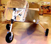
The heavy-duty tricycle gear system was chosen as the standard gear configuration for the ZODIAC CH 640 to meet the needs of today’s pilots: Most pilots are not experienced ‘taildragger’ pilots, and a tricycle gear provides better stability and control on the ground.

 |
Borrowed from the ZENITH CH 2000, the CH 640 utilizes a heavy duty gear system developed specifically for flight training operations (hard landings!). The main gear is a simple single-piece ¾-inch thick aluminum spring leaf. The single carry-through main gear provides double cantilever deflection. Four large bolts hold up the gear to the fuselage bottom which is reinforced by thick welded steel braces. |
While it’s not the lightest gear system around, it provides excellent grass-field capability, and is very durable, simple and virtually maintenance-free. The fixed gear ZODIAC CH 640 is equipped with three 5.00 x 5 wheels, or optional 6.00 x 6 wheels.
The nosewheel strut uses a single heavy-duty bungee for shock absorbency. The nosewheel is steerable, with direct linkage to the rudder pedals for very effective and responsive ground handling and tight turns. The main wheels are equipped with independent hydraulic disk brakes.
The ZODIAC CH 640's gear has been developed to allow grass-field operation, and the direct linkage steerable nosewheel, plus differential breaking, provide remarkably precise ground handling and steering.

Single disc hydraulic brake assemblies are provided on the main gear. The classic Cleveland wheels with matching hydraulic disc brakes are used, made from magnesium alloy casting to give a lightweight durable unit. The aircraft comes with standard 6 ply tires.
The brakes are actuated by toe brake pedals which are attached to the rudder pedals. The master cylinders with reservoirs are connected to the pedals on the pilot side, and standard master cylinders are on the passenger side. No additional brake fluid reservoir is used. Both master and slave cylinders are the traditional Cleveland units. Brake lines are made of clear heavy duty nylon tubing. This makes it easy to bleed the brakes and very easy to install and remove the lines.
The nose gear is steerable through a 14 degree arc each side of center by the use of the rudder pedals. Steel 3/8 inch diameter rods connect the rudder pedals to the nose wheel. This gives the aircraft accurate and tight steering. A bungee assembly on the nose strut dampens shock and bumping during taxiing. The nose wheel design is unique in that it is very simple. The nose wheel strut is held in place with two large nylon bearings, impregnated with oil. The lower bearing is machined so that the strut "self centers" which also centers the rudder. A heavy duty bungee pushes down the nose strut and flexes on touchdown. The nose wheel is attached to a ¾ inch thick aluminum wheel fork which is bolted to the nose strut. The nose strut is 2 inch diameter 4130N steel tubing. The result is an all around extra tough nose gear assembly which has no O rings, back-up rings or gaskets. Additionally, no shimming is required.
Optional wheel fairings give a sleek look to the aircraft. They are made of a two part fiberglass shell and are easily removed or mounted to their attachment brackets.
Instrument panel
The instrument panel was designed to accommodate the standard instruments for VFR flights, with plenty of room to install the optional avionics and IFR instruments.

Standard recommended instruments include a compass, an airspeed indicator (ASI), a tachometer (RPM), sensitive altimeter (ALT), an ammeter, and the engine instrument cluster. The compass is mounted above the dashboard in clear view of the pilot and co-pilot.
The flight instruments are mounted on an aluminum sub panel and held in place with standard vibration isolation rubber mounts, maximizing instrument life by minimizing vibrations. The airspeed indicator, RPM, and engine cluster gauges are the only instruments that have special markings. All other gauges are TSO’d and can be purchased locally.
Engine cluster gauges. The gauges in the engine cluster are unique in that each gauge is installed separately from the front, making them simple to maintain. The cluster includes: fuel pressure, oil pressure, left fuel quantity, right fuel quantity, amp meter, and volt meter. Engine sending units are heavy duty standard units from VDO. The fuel level sender units are standard Stewart Warner type which are float operated.
The pitot static pressure system supplies both pitot and static pressure for the airspeed indicator, altimeter, and the optional vertical speed indicator. Pitot and static pressure are picked up by a pitot head installed on the bottom of the left wing and carried through pitot and static lines within the wing and fuselage to the gauges on the instrument panel. When the IFR airframe option is installed, two heater elements are installed in the pitot head, and an alternate static switch is installed on the instrument panel.
The optional gyro package includes a vertical speed indicator, an attitude gyro (artificial horizon), a directional gyro, and a turn and slip indicator (turn coordinator).
The wing tie-down rings and the tail skid make it easy to tie down the aircraft. The wing tie-down rings are attached to the aircraft wing main spar. The tail skid is attached to the fuselage bottom. The tail skid is also used for hard tail landings and is made out of 2 inches by 3/8 inch thick aluminum. It is held in place with one bolt at one end and is sandwiched at the other so that it can flex, acting as a small landing gear.
The electrical system of the Zodiac CH 640 is a 12-volt direct-current single-wire negative-ground system. Electrical equipment is grounded to the metal structure of the airplane, taking place of the second wire. A 12 volt "Gill 35" battery is incorporated in the system to furnish power for starting and as a reserve power source in case of alternator failure. The battery and alternator are both connected to the bus bar from which all the electrical equipment is powered. The starter receives its power from the load side of the battery. The master switch, located on the switch panel below the instruments, controls the battery relay. The master switch must be on before any electrical equipment will operate.
The electrical switches and circuit breakers are installed on sub-panels which are screwed to the main instrument panel. This makes it easy to remove and install new switches and breakers. Instead of using switches and separate breakers for each ON/OFF system, combination single pole switches and circuit breakers are used instead.
The charging system consists of a 3 phase, delta-connected alternator (with the Lycoming O-360) rated 14V D.C. at 70 amp continuous output. Overvoltage protection is provided within the regulator. It will trip the regulated output after the regulator fails to maintain the correct level.
----
The ZODIAC XL features a completely new wing design for increased capability. The XL design features a new airfoil and a larger wing area than the ZODIAC CH 601 HDS model, which allows the XL design to achieve higher speeds with a higher payload. With the addition of wing flaps, the stall speed has been kept low for recreational pilots.


- The profile of the ZODIAC XL wing is 15% thick (Riblett GA 35-A-415 airfoil).
- Plan Form: The wing is slightly tapered with a straight spar and leading edge
- Ailerons and flaps on the trailing edge.
- Wing dihedral is standard, starting at the fuselage.
While the XL wing design is new, the simple construction techniques that have made the ZODIAC famous have remained the same.

Wing
Specifications:

Top view of the new ZODIAC XL wing
Ailerons:
The large ailerons provide precise and light roll control. The standard
ailerons are attached to the wing with a unique "hingeless" system, flexing
the aileron skin which is riveted to the top of the wing trailing edge. [Click
here for additional details on the "hingeless" ailerons.] Alternatively,
a conventional "piano hinge" can be used.

The ZODIAC XL has been configured to take full advantage of its increased useful load. The fuel is located in dual welded-aluminum wing tanks. The standard dual wing tanks offer a fuel capacity of 24 US gallons. Long Range fuel tanks are optionally available, which increase the total capacity to 30 US gallons (2 x 15 gallons) to provide superior range and endurance.

Welded Aluminum Wing Tank:

 |
The tail sections (empennage) of all
ZODIAC models are the same. Many builders start construction of the aircraft with the tail sections. These low-cost sections are the smallest components of the aircraft and can easily be built in a small workshop. |

RUDDER TAIL SECTION:

| The ZODIAC tail sections are designed to provide maximum effectiveness (control) at slow speeds. The aircraft designs feature an all-flying vertical tail (rudder) section for excellent effectiveness and control, especially at low speeds. The all-flying rudder provides responsive rudder control, while also minimizing weight and complexity (there’s only one vertical tail section). Two rudder bearings bolt to the rear fuselage to fix the rudder to the fuselage. |
 |

HORIZONTAL TAIL SECTIONS:

The horizontal stabilizer tail section is built up of two spars and eight internal ribs, with reinforcement doublers on the spar for the spar attachment brackets.
The internal assembly is then covered with the pre-formed sheet-metal skin. The skin is wrapped around the internal assembly, and drilled and riveted into place. Rounded fiberglass fairings are riveted to the tips of the elevator. The elevator is bolted to the top of the rear fuselage.
The elevator is constructed of a single pre-formed skin with reinforcing internal ribs. It is attached to the stabilizer with a conventional piano-hinge, and is equipped with a standard electric trim tab.

Note that some of
these view may not be to scale.
 |
General View of the
ZODIAC XL, with a Continental O-200
engine installation. Click photo for large view |
 |
General View of the
ZODIAC XL Click photo for large view |
 |
General View of the
ZODIAC XL, with a Continental O-200 engine installation. Click photo for large view |
 |
General Assembly Schematic, with Open Canopy |
 |
Great Underside View of the ZODIAC XL |
 |
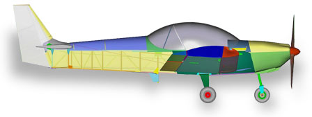
Side View, with a Continental O-200 engine installation. |
 |
Top View
|
 |
Front View |

|
|
| Additional detailed schematics: | |
 |
Side View, Open Canopy.
|
 |
The ZODIAC XL Wing Assembly: Right Wing, view for the rear |
 |
The ZODIAC XL Wing Assembly: Right Wing, view for the front |
 |
The ZODIAC XL Wing Assembly: Right Wing, view for the rear |
 |
Horizontal Tail Assemblies |
 |
Rear Fuselage Assembly |
 |
ZODIAC XL Fuselage Assembly - Control System Detail |
 |
Continental O-200 installation |

Note: These schematics are for illustrative purposes only.

The fuselage is built in modular sections: the rear fuselage and the forward fuselage assemblies are first built separately, and then joined together.
The rear fuselage has a basic rectangular section with a rounded top. The bottom fuselage is flat, and aesthetically rounded at the front to join the sleek fiberglass engine cowl.

Rear Fuselage Assembly
The fuselage is built up in stages and requires no special assembly fixtures - it is simply built up on the flat workbench:
|
Building the rear fuselage: |
|
 |
 |
| The fuselage bottom | Right fuselage side attached |
 |
 |
| Fuselage assembly with sides | Tail sections attached... |
The top rounded fuselage bulkheads are then positioned to the lower fuselage sides and the top fuselage skin is simply wrapped around the bulkheads:

The forward fuselage section (cabin area) is build separately, and then joined to the rear fuselage section.

Forward-Fuselage / Cabin Assembly


|
WING CONSTRUCTION |
Construction of the ZODIAC wings is typically the next stage in the modular assembly process - the tail sections and wings do not require a lot of space for storage once assembled, unlike the fuselage / center section assembly.

 |
The beefy wing spar is made up of three sections: a fuselage center section and the outboard wing panels, which are bolted to the center spar (for quick and easy wing removal). The spar sections come completely pre-assembled in the kit (drilled and riveted, with flanged lightening holes). |
| The structural aluminum wing ribs and bulkheads are supplied ready-to-install (pre-formed and finished by hand at the factory). |  |
The outboard wing spars are built up "C"-beams with spar cap angle extrusions at the top and bottom. The center section spar is similarly fabricated. Upon completion at the factory, the three wing spar sections are positioned at the dihedral angle of 6.5 degrees and joined by two 1/8-inch splice plates. This step ensures that the wing assembly maintains the correct wing alignment once the center section is attached to the fuselage. In the kit, the spars are supplied factory-built, with the wing dihedral already preset.

The nose ribs and rear ribs are positioned along the spar and drilled and riveted (with the Avex blind rivets) into place. The wing spars are supplied with pre-drilled rib stations. A rear "Z" spar channel is attached along the end (trailing edge) of the rear ribs.
Before the top skin is drilled and riveted, care is taken to level the spar/rib assembly on the flat work bench. The wing has no washout twist so it is a simple matter to align the flat ribs bottoms in one plane (flat on the workbench). The drilled surface sheet-metal skins are blind riveted using Avex rivets to the main spar and the rear wing ribs, leaving the trailing edge temporarily unattached, where the aileron skin will be positioned later.

Chord-wise "L" angle stiffeners are located and riveted in the middle of each rib bay. Structural reinforcement angles are added to specific areas of the wing tip and the luggage locker. Most skins in the kit are pre-drilled, are cut to size and are pre-formed, ready for assembly.

The wing assembly is then turned over on the workbench, and the bottom wing skin is positioned, drilled and riveted to the wing assembly.

The next step is the attachment of the leading edge skin. The preformed skin laps over the top and bottom skins. Working from the bottom rear to the front, the located skin is drilled and clecoed into the spar and nose ribs. Using ratchet straps the skin is pulled tightly over the front wing ribs. With the wing aligned, additional holes are drilled, clecoed and finally riveted.


The unique "hingeless" ailerons are made up of a simple pre-formed single sheet-metal skin with five internal ribs. Eight equally spaced rivets attach each rib to the aileron skin. A aileron horn is riveted to the inboard rib. A unique feature of the Zodiac is the addition of wing washout to the ailerons (as the wing is built flat with no twist). A slight twist is created by shimming the aileron tip and riveting the assembly closed. The 40 mm extension of the upper aileron surface acts as a hinge when riveted to the rear of the wing (between the skin and the "Zee" section layers).
 |
 |
The top aileron skin extends to the wing trailing edge, where it is riveted to the wing assembly. The top aileron skin flexes to provide aileron deflection, while providing a very effective gap seal. A piano-hinge can be substituted for the hingeless aileron.

The wing baggage locker is positioned behind the main spar, between the first and second rear ribs, and a rear panel is positioned. The baggage door is supplied pre-formed, and is hinged at the front for opening. "Dzus" fasteners are used to fasten the door closed. Optional wing tanks can also be installed in the wing baggage lockers.

The center wing section is built next, constructed the same as the outer wing sections. The center section assembly consists of the main spar, the rear spar channel, ten nose and rear ribs, and the outer skins. Reinforcement brackets are positioned where the main landing gear will be installed.

The center wing assembly will become part of the forward fuselage / cabin assembly.

|
FUSELAGE CONSTRUCTION |

The fuselage is built up in stages and requires no special assembly fixtures - it is built up on the flat workbench. The fuselage is built in modular sections: the rear fuselage and the forward fuselage assemblies are first built separately, and then joined together.

Construction begins with the assembly of the rear bottom skin, angle longerons, panel stiffeners and local reinforcements. The flat rear fuselage sides are then each built up separately on the workbench, and then joined to the bottom. Unlike other structural materials, aluminum construction allows for occasional mistakes since rivets can be drilled out.
The bottom rudder hinge plates are attached to the bottom skin and two horizontal tail frames (bulkheads) are drilled and clecoed in place, and the round fuselage top bulkheads are positioned to the rear fuselage assembly.

Pre-formed longeron angle extrusions produce the curved fuselage, and are used to join the rear fuselage assembly to the center wing section and the steel firewall bulkhead. The cabin floor skin is fitted under the center wing assembly and longeron angle extrusions are added, reinforcing the join from the firewall to to rear fuselage.

Additional forming stiffeners are added into place, and the forward fuselage sides are fabricated and positioned next from the pre-cut skins. The rear baggage floor is then drilled and riveted into position.
 |
 |
| ZODIAC fuselage / center wing assemblies | |
Fuselage and cabin parts are supplied pre-formed from the factory, as standard parts that make up the complete kit.

Installation of the cabin seat parts, instrument panel, and seat belt attachment points completes the basic fuselage assembly, followed by attachment of the tail sections to the rear fuselage and installation of the pre-formed rear fuselage top skin.
Fuselage Assembly Overview


The ZODIAC is a sleek and docile aircraft, ideal for both local and long cross-country flights. All ZODIAC models offer comfortable two-place side-by-side seating in an ergonomically designed 44-inch wide cabin. The huge tinted bubble canopy, which provides outstanding 360 degree visibility, is hinged on both sides of the cabin, to allow access from either side of the aircraft. Access to the cabin is easy over the 20-inch wide reinforced wing walkway on both sides of the cockpit, and facilitated by a ‘step’ located below the trailing edge of the wing.

The ZODIAC design is the product of extensive research and development,
and the result of professional engineering by Chris Heintz, a leading
designer of light aircraft. The modern ZODIAC design makes use of advanced
technologies, while using proven design concepts and simple systems for easy
assembly and maintenance. A professional design, the ZODIAC structure has
undergone a complete and rigorous flight test and design stress analysis.
Developed for the inexperienced first-time builder and demanding
recreational pilot, the ZODIAC aircraft is designed to be easy to build and
to maximize flight performance and efficiency.

Simple systems, modern materials, and design ingenuity minimize required maintenance, and make the ZODIAC easy to build and fly, affordable, and very durable.

ZODIAC CH 601 WING The ZODIAC wings are made up of a single cantilevered spar with near full-span non-hinged ailerons.
The CH 601 and CH 601 HD models use a simple constant-chord airfoil, while the CH 601 HDS and the new ZODIAC XL feature tapered ‘speed’ wings.
 |
The high-lift low-drag airfoils
provide an efficient cruise speed, as well as desired slow flight and
gentle stall characteristics. Flaps are not required with the high-lift
wing designs of the ZODIAC. The outboard wing panels can easily be
removed in 15 minutes each for trailering and storage. With the wings
removed, the fuselage fits through the door of a standard single-car
garage and can be trailered. |
The rear fuselage has a basic rectangular section with a rounded top. The bottom fuselage is flat, and aesthetically rounded at the front to join the sleek fiberglass engine cowl. The classic horizontal tail has a stabilizer and elevator, which is equipped with a standard electric trim tab.
The ZODIAC CH 650 is the new model of the ZODIAC kit aircraft series, optimized for the Sport Pilot category. The ZODIAC features a completely new wing design, landing gear and fuselage. The tail sections are the only components common with all ZODIAC models.

The ZODIAC design is the product of extensive research and development, and the result of professional engineering by Chris Heintz, a leading designer of light aircraft. The modern design makes use of advanced technologies, while using proven design concepts and simple systems for easy assembly and maintenance. A professional design, the ZODIAC structure has undergone a complete and rigorous flight test and design stress analysis, as well as load testing of critical components.
Developed for the first-time builder and demanding recreational pilot, the
ZODIAC aircraft is designed to be easy to build and to maximize flight
performance and efficiency.
Simple systems, modern materials, and design ingenuity minimize required maintenance, and make the ZODIAC simple to build and fly, affordable, and very durable... an aircraft you'll be proud to own and fly for many years.
While the ZODIAC design is new, the simple construction techniques that have made the ZODIAC famous have remained the same. In fact, many design features of the new ZODIAC CH 650 model make it the quickest and easiest ZODIAC model to build.
The handling characteristics of the ZODIAC are very good and quite similar to the previous ZODIAC models, with just slightly higher roll control forces (this was predictably the result of a larger chord aileron). The new airfoil section is thinner than previous ZODIAC models, and was chosen for reduced drag (higher top end speed). Wing flaps were added to minimize stall speed with the new lower-drag airfoil. Following flight testing of the prototype ZODIAC XL by designer Chris Heintz, aircraft stability within the useful center of gravity (CG) range was found to be very satisfactory, and incipient spin tests did not show any tendencies toward a flat spin. Spin recovery is conventional and fast.
Throughout, construction of the ZODIAC kit aircraft is ‘modular’ – each section of the aircraft is built separately on the workbench. Many builders thus choose to buy ‘component kits,’ purchasing kit sections as they progress through the project. The modular construction of the kit means that required workshop space is minimal – most builders construct the kit in a single-car garage or basement workshop.

Once all the airframe sections have been assembled, the wing and tail sections are bolted to the fuselage and the landing gear, controls, and fuel systems are installed. The wings are designed for easy removal for occasional trailering of the aircraft.
|
SPECIFICATIONS ZODIAC CH601 XL |
Jabiru 3300 | Rotax 912S (100 hp) |
Lycoming O-235 (116 hp) |
|||
| WING SPAN | 27 FT. | 8.23 m. | 27 FT. | 8.23 m. | 27 FT. | 8.23 m. |
| WING AREA | 132 SQ. FT. | 12.3 m.sq. | 132 SQ. FT. | 12.3 m.sq. | 132 SQ. FT. | 12.3 m.sq. |
| LENGTH | 20 FT. | 6.1 m. | 20 FT. | 6.1 m. | 20 FT. | 6.1 m. |
| HORIZONTAL TAIL SPAN | 7 FT. 7 IN. | 2.30 m. | 7 FT. 7 IN. | 2.30 m. | 7 FT. 7 IN. | 2.30 m. |
| RUDDER TIP HEIGHT | 6 FT. 6 IN. | 1.98 m. | 6 FT. 6 IN. | 1.98 m. | 6 FT. 6 IN. | 1.98 m. |
| EMPTY WEIGHT | 695 LB. | 318 kg. | 690 LB. | 312 kg. | 800 LB. | 362 kg. |
| USEFUL LOAD | 625 LB. | 282 kg. | 630 LB. | 285 kg. | 520 LB. | 235 kg. |
| GROSS WEIGHT | 1,320 LB. | 595 kg. | 1,320 LB. | 595 kg. | 1,320 LB. | 595 kg. |
| WING LOADING | 9.85 psf | 48 kg/sq.m. | 9.85 psf | 48 kg/sq.m. | 9.85 psf | 48 kg/sq.m. |
| FUEL CAPACITY (wing tanks) | = 24 Gal. (US) |
2 x 46 l. = 92 l. |
= 24 Gal. (US) |
2 x 46 l. = 92 l. |
= 24 Gal. (US) |
2 x 46 l. = 92 l. |
| POWER LOADING | 11.8 LB./HP | 5.3 kg/HP | 13 LB./HP | 5.9 kg/HP | 11.2 LB./HP | 5.1 kg/HP |
| CABIN WIDTH | 44 INCHES | 112 cm. | 44 INCHES | 112 cm. | 44 INCHES | 112 cm. |
| LOAD FACTOR (G) ultimate | +/- 6 g | +/- 6 g | +/- 6 g | |||


NOTE: Specification figures are based on standard factory prototype test results, and are subject to change and revision without prior notice.


Made for the first-time kit builder, the ZODIAC may be built from plans-only, or from partial or complete kits. Building a ZODIAC from scratch (rather than a kit) necessitates more time, skills, and tools, requiring about 1,500 hours to build.

Click here
for a detailed schematic of the tail control system
All the ZODIAC CH 601 models draw on Zenith Aircraft’s vast design and manufacturing experience. The simple stressed-skin semi-monocoque construction uses single curvature sheet-metal skins riveted to internal structural members.
Drawings & Manuals

Supplied with the complete ZODIAC kit, the drawings are not just assembly instructions (as with most kits), but are detailed 11" x 17" CAD blueprints of the entire airframe assembly, and come with an assembly manual. Supplied with a serial number, you can actually build your own aircraft from "scratch" following the drawings and manuals. If purchased separately, the cost of the drawings and manuals is deductible off the cost of the full kit.

Click here for details about the new ZODIAC XL
Drawings and Manuals.
Builders that have previously purchased the Drawings and Manuals for the
ZODIAC CH 601 UL, HD or HDS models can update their drawings to the latest
edition. Click here for more info.
|
Following are some selected sample CAD drawings from the ZODIAC CH 601 HD drawings. These are sample drawings only, and are for informational and educational purposes only.
| Fuselage General Arrangement | 6-0 | image |
| Fuselage Exploded View | 6-F-0 | image |
| Firewall | 6-F-8 | image |
| Firewall Installation | 6-F-9 | image |
| Instrument Panel / Bulkheads | 6-F-12 | image |
| Tail Control Cables | 6-F-15 | image |
| Rudder Pedals / Brakes | 6-F-18 | image |
| Landing Gear | 6-L-0 | image |
| Landing Gear Detail | 6-L-3 | image |
| Tail Sections | 6-T-0 | image |
| Rudder Detail | 6-T-5 | image |
| Wing Assembly | 6-V-0 | image |
| Wing Ribs | 6-V-1 | image |
| Internal Wing Structure | 6-V-3 | image |
| Center Wing / Main Gear | 6-V-6 | image |
| Wing Skin Riveting | 6-V-9 | image |
| Seat Arrangement | 6-V-12 | image |
| Aileron Bellcrank Control | 6-V-14 | image |
| Wing Attachment & Aileron Control | 6-V-15 | image |


Uçak Yapım Atölyesi ( ZODIAC CH 640 DESING AND CONSTRUCTION)
Hiçbir yazı/ resim izinsiz olarak kullanılamaz!! Telif hakları uyarınca bu bir suçtur..! Tüm hakları Çetin BAL' a aittir. Kaynak gösterilmek şartıyla siteden alıntı yapılabilir.
© 1998 Cetin BAL - GSM:+90 05366063183 -Turkiye/Denizli
Ana Sayfa / Index / Roket bilimi / E-Mail / Kuantum Fizigi / Astronomy
/ Time Travel Technology / UFO Galerisi / UFO Technology /