Electromagnetic Radiation and Radio Waves
(Natural and Man-Made Miracles)
Electromagnetic Radiation
Electromagnetic radiation is a wonderful thing. It brings us heat and lights up our day, it brings us radio and television and carries our telephone conversations. It brings us the Sun's energy which is needed by all plants for photosynthesis and growth. It brings warmth to the inhabitants of the Earth's animal kingdom and to some of them to tan their bodies. We also use it to see through solid bodies, to find our way around the planet and to cook our food.
In a tremendous intellectual leap, in 1873 James Clerk Maxwell suggested the existence of electromagnetic waves and worked out mathematically what their properties might be before anybody had ever observed, or even thought of, such a phenomenon. Since then, communications engineers have performed miracles harnessing this radiation for a myriad of uses.
Electromagnetic radiation has the following interesting properties
- It can be found in nature or be man-made.
- It does not require a medium for propagation.
- It travels with the speed of light.
- It carries energy as it propagates. The higher the frequency, the higher the energy associated with the wave.
- It can transfer its energy to the matter on which it impinges.
- Its transferred energy may be sufficient to break chemical bonds, ionising the matter on which it impinges.
- Its propagation obeys the inverse square law.
- It can be used to carry information.
- It can be broadcast outwards to reach many locations or it can be formed into beams to reach a particular spot.
- It can be be reflected or refracted.
- It can be split and recombined to form diffraction patterns.
- It can travel great distances. The radiation resulting from a simple100 volt, 1 MHz sine wave fed into a suitable antenna can be detected as far away as the next planet.
- It travels in straight lines.
- It can be bent around the Earth's circumference by reflection from the ionosphere.
- It can pass through walls.
- It can be captured by placing a metal rod, a loop, parabolic metal dish or horn in its path and it can be launched into the atmosphere with the same tools.
Radio Waves
Radio waves are a specific example of electromagnetic radiation. Despite all the communications benefits "electromagnetic radiation" makes possible, the name has a sinister connotation. The alternative name, "radio waves", does not seem nearly so threatening. But too much of a good thing, even water, can be dangerous if present in excessive quantities at the wrong place or time. So it is with electromagnetic radiation.
We are in fact swimming in an ocean of radio waves of various strengths. At home we have high frequency radiation coming from
- Hundreds of long wave, medium wave. short wave and UHF radio broadcasts
- Dozens of terrestrial television signals
- Television signals at microwave frequencies beamed down by satellites
- UHF signals from hundreds of mobile phones and their local base stations
- VHF Private mobile radio signals used by the emergency services and private networks
- Television remote controls
- Remote control toys (cars and planes)
- Microwave GPS satellite navigation location signals whether we use them or not.
- Wi-Fi networks for communications between computers and computer networks
- Bluetooth connections between electronic appliances
- Laser light in CD players
- Infra red television remote controls
- Wireless security sensors
- Garage door openers
- Car door remote locking keys
- Infra red radiation from cookers and domestic heaters
- Leakage from microwave ovens
- Continuous unwanted radio frequency interference (RFI) generated by computer circuit boards and oscillators in radio reception and transmission equipment
- Random RFI due to local electrostatic discharges from motor commutators on household equipment and power tools as well as automobile ignition systems (sparking plugs).
- Random RFI due to distant electrostatic discharges from lightning strikes anywhere between the signal source and the home
And at the other end of the spectrum we have
- Very low frequency radiation from power cables, electric motors, domestic appliances, transformers and battery chargers.
Depending on where we live we may also be near enough to experience signals from other sources even though we may not have the equipment to capture them
- Air traffic control systems
- Aircraft instrument landing systems
- Radar surveillance
- Microwave repeater systems used for broadband communications links
- Speed cameras
- Very low frequency radiation from electric fields radiating from high voltage electricity grid transmission lines, transformers and power cables.
Closer to home we submit ourselves to high levels of radiation from medical equipment
- X Ray machines
- X Rays from CAT scanners
- Electromagnetic fields from MRI scanners
But curiously many hospitals ban the use of mobile phones because their tiny transmitters might interfere with sensitive medical equipment.
Then we are all bathed in more general background sources of radiation most of which we can not avoid and some we can.
- High frequency radiation from the Sun and other artificial light sources at optical frequencies
- Infra red radiation (heat) from the Sun
- Man made heat and light sources
High energy, short wavelength electromagnetic radiation such as ultra-violet rays, X rays and gamma rays can cause ionisation of other materials when present at high enough energies and this can cause serious and permanent damage to human tissue. This radiation may be found in nuclear installations and may also be used in controlled medical treatments. Such radiation may be found in the domestic environment but fortunately not at dangerous levels.
- Low level X rays from high voltage cathode ray tubes (CRT) formerly used in colour televisions and monitors
- Ultra-violet lamps and tanning equipment
- Gamma rays not normally present in the home
The first man-made radio waves were created in 1888 by Heinrich Hertz, three years after the world's first practical automobile was launched by Karl Benz. Before that, apart from light waves and the odd lightning discharge, there were almost no radio waves in the atmosphere. The growth of radio waves in the atmosphere in the last one and a half centuries has followed the growth of industrial development, just like the concentration of carbon dioxide in the atmosphere, but at least radio waves have not been blamed for global warming. (Not yet anyway!)
Communications and Engineering Miracles
- With all these radio signals vying for our attention, amongst a background of unwanted radiation sources, all whizzing by with a speed of 186,000 miles per second, thanks to communications engineers you can poke your mobile phone or radio antenna into the air and select just the signal that was intended just for you.
- The very limited bandwidth available within the electromagnetic spectrum, which is suitable for radio communications, accommodates millions of communications links with a collective bandwidth of many times the available bandwidth by simultaneously using the same frequencies without interfering with eachother. Another set of challenges answered by communications engineers.
- We might also expect that all the radio signals in the atmosphere would be completely scrambled with each other. Fortunately by some natural miracle the signals retain their integrity. They may be superimposed on eachother or swamp eachother and they may pick up electrical noise during their travels but they do not mix to form sum and difference frequencies as they would in a non linear device and so no miraculous engineering solution is needed to decode or operate upon the new frequency components to reconstruct the original signal. They only need to be separated from each other.
The Electromagnetic Wave
Maxwell's equations describe how electromagnetic radiation is propagated. He showed that a varying magnetic field induces an associated varying electric field perpendicular to the magnetic field and this varying electric field in turn induces an associated varying magnetic field in the plane of the initial magnetic field. Together these two varying fields form an electromagnetic wave propagating at the speed of light in a direction perpendicular to both the electric and magnetic fields as shown in the diagram below.
 |
Source - G.R. Delpierre and B.T. Sewell, University of Capetown (Modified)
Radiation Wavelength and Frequency
The frequency f (Hertz) of the wave is inversely proportional to the wavelength λ (metres) and is given by the relationship
f = c / λ
where c is the speed of light (m/sec).
Radiation and the Inverse Square Law
The rate at which energy emanating from a fixed, constant source of electromagnetic radiation passes through a surface at a distance d from the source is proportional to 1/d2. This is known as the Inverse Square Law. It arises simply because the surface enclosing the source is a sphere, centred on the source, through which all the energy must pass and the surface area of this sphere increases as the square of the distance d from the source. Thus the energy flow (measured in Watts per square metre (W/m2)) falls off rapidly as the distance from the source increases.
Radiation and Polarisation
The individual electric and magnetic fields in an electromagnetic wave are orthogonal (at right angles) to eachother with the plane of oscillation of the fields determined by the orientation of the radiating element such as an antenna. By convention the polarisation refers to the plane of oscillation of the electric field.. In the diagram above the polarisation is vertical as represented by the direction of the electrical field E and is said to be linear.
Electromagnetic waves may also be circularly polarised, in which case, the tip of the electric field vector E, describes a helix along the direction of propagation. Such waves may be generated from two crossed dipoles fed with a 90° degree time-phase difference (phase quadrature) or by a helical antenna radiating in the direction of its axis.
The Electromagnetic Wave Spectrum
Electromagnetic waves can typically be described by any of the following three physical properties: the frequency f, wavelength λ, or photon energy E. The diagram below shows all possible frequencies of electromagnetic radiation and the corresponding photon energies and some of the applications for which they are used. The spectrum covers an enormous range with wavelengths ranging from the size of an atom to almost the size of the universe, (Over 26 orders of magnitude). The corresponding photon energies occupy a similar range, from the unmeasurable to the highly dangerous.

Wave - Particle Duality
Quantum mechanics wave - particle duality theory showed that paradoxically, electromagnetic radiation and particles of matter could exhibit both wave-like and particle-like properties but not at the same time. In practice this means that some properties of radiation can best be explained by wave theory while others can better be explained by particle theory which describes electromagnetic radiation as an energy flow carried by particles called photons, each with a characteristic energy which depends on the frequency of the radiation.
Photon Energy
The photon energy E of a single photon associated with the electromagnetic wave increases with frequency and is given by the relationship
E = h x f (Joules) or h x c / λ
where h is Planck's constant (6.63 X 10⁻³⁴ Joule seconds or 4.14 X 10⁻¹⁵ eV seconds) and f is the frequency of the wave and c is the velocity of light (299.8 x 10⁶ m/sec) .
Examples:
- The spectrum above shows that the individual photons in visible light
have energies of a few electron Volts while the particles in cosmic rays
with an equivalent frequency of around 1025 Hertz have
relatively enormous energies of over 10 billion electron Volts (1.6
nanoJoules). Though a nanoJoule is very small, the total energy flow
associated with the radiation is many, many times greater due to the very
high number of photons making up the overall photon flux (See below).
- Below a frequency of around 100 GHz, which includes most of the spectrum used for radio communications, the energy of individual photons is almost negligible at less than 10−4 eV or 10−24 Joules.
The photon flux Φ of a radiated wave, defined as the number n of photons per second per unit area of the wave is given by
Φ = n/m2/sec
The energy E associated with the photons is given by
E = n x h x f(Joules)
The radiation intensity P or power density (radiated power per unit area) associated the photon flux is given by
P = Φ x E = n x h x f / sec / m2 (Joules / sec / m2 or Watts / m2)
The number of photons n in E Joules of energy at any frequency or wavelength is given by
n = E x h / f = E x h x λ / c
The number of photons per Joule (setting E = 1Joule) for light is given by
n = h x λ / c
Note that a the radiation intensity depends on BOTH the photon flux AND the frequency of the radiation.
Examples:
- Common Light Sources
- For visible green light with a wavelength λ = 500 nm (500 x
10-9 metres)
The photon energy E = h x c / λ = (6.63 X 10-34) x (299.8 x 106) / (5 x 10⁻⁷) = 3.98 x 10⁻¹⁹ Joules or 2.48 eV
The number of photons per Joule of radiated energy is = 1 / ( 3.98 x 10⁻¹⁹) = 2.513 x 10¹⁸ (a very large number!)
- Making some gross assumptions we can calculate the rate at which
photons are emitted by a 100 Watt incandescent light bulb.
- The rate energy is supplied to the lamp = 100 Watts = 100 Joules per second.
- But only about 2.25% of this energy is converted to visible light. (See Energy Efficiency) Thus the lamp emits 2.25 Joules of radiant light energy per second.
- The lamp actually emits a wide spectrum of radiation, most of which is infra red radiation but we are only considering the visible energy here which amounts to about 10% of the total radiated energy. The visible energy is emitted over the spectrum from red to violet (wavelength 7.5 X 10⁻⁷m to 3.5 X 10⁻⁷m) with varying intensity, but for the purposes of this calculation we can assume that the average wavelength of the radiation is 5.0 X 10⁻⁷m which is the wavelength of green light near the middle of the visible spectrum. See the graph of Solar Radiation which has a similar spectrum and also the Electromagnetic Wave Spectrum above.
- From the above, the rate at which visible light photons are radiated from a 100 Watt incandescent light is 2.25 x 2.517 x 1018 = 5.66 x 10¹⁸ photons per second.
- The total number of photons emitted per second over the full
radiation spectrum of the light source (heat and light) will depend on
the temperature of the source and will be about 10 times the number of
photons contained in the visible light.
- For visible green light with a wavelength λ = 500 nm (500 x
10-9 metres)
- Cosmic Radiation
Cosmic radiation is not strictly electromagnetic radiation. Cosmic rays are in fact streams of high energy particles originating from outside the earth's atmosphere. They are not homogenious and may have different constituent particles. Typically they consist mainly of protons, (positively charged Hydrogen nuclei) which make up around 89% to 90% of the stream, alpha particles (Helium nuclei) which make up around 9% of the stream, the nuclei of other heavier elements which account for about 1% of the particles and beta particles (electrons) make up the remaining 1%. Similarly the cosmic ray particles may have different energy levels with particles originating from the sun, the so called "solar wind" having relatively low energy levels of around 106 eV, while particles emanating from outside the solar system typically have energy levels ranging from about 108 to1012 eV, though energy levels of up to 1021 eV have been recorded. This is many orders of magnitude greater than the 1013 eV which the best terrestrial particle accelerator, CERN's Large Hadron Collider (LHC) can produce.
Before the invention of particle accelerators such as the cyclotron and the synchrotron, nuclear physics experimentors often used cosmic rays as the source of high energy particles in their experiments.
See also Cosmic Rays - History
Being composed of sub-atomic particles, cosmic rays do not propagate with the speed of light, but at some speed close to it. Their particle energy levels are close to the photon energies in the higher frequency electromagnetic waves and simply for convenience, cosmic rays are often included in graphical representations of the electromagnetic spectrum with an equivalent wavelength or frequency for their energy levels (as in the diagram above).
Similar to nuclear radiation, the high energy cosmic ray particles can cause ionisation of materials on which they impinge and as such can have dangerous physiological effects. See Physiological Effects of Electromagnetic Radiation (below) and Physiological Effects of Nuclear Radiation.
Fortunately the earth's magnetic field deflects much of the cosmic radiation away from the earth and some of what get's through is absorbed by the earth's atmosphere. Nevertheless, cosmic radiation accounts for about 13% of all background radiation at the earths surface. The radiation dose at the earth's surface attributable to cosmic radiation amounts to about 3.6 milliSieverts (mSv) whereas the dosage from all sources of background radiation (including the nuclear decay of the earth's elements) is around 3.0 mSv in the USA and 2.0 mSv in the UK. The cosmic energy dosage however increases with altitude which can be a health hazard for airline crews and frequent fliers and is positively dangerous for astronauts. It is estmated that cosmic rays contribute to 100,000 cancer deaths per year.
- For cosmic radiation with an equivalent wavelength of 10-16
metres:
The photon energy is (6.63 X 10-34) x (299.8 x 106) / (10-16) = 1.99 x 10⁻⁹ Joules or 1.24 x 10⁹ eV
The number of photons per Joule is = 1 / (1.24 x 10⁹) = 5.03 x 10¹⁰
Note that as a consequence of the shorter wavelength, each photon of cosmic radiation contains 5 x 10⁹ times as much energy as the green light photons and can consequently be much more damaging. (See following section)
By the same token, green light radiation needs correspondingly 5 x 10⁹ more photons to make up one Joule of radiated energy than cosmic radiation because of the lower energy level of the photons emitted by green light.
- For cosmic radiation with an equivalent wavelength of 10-16
metres:
Ionisation Effects of Electromagnetic Radiation
Ionisation is the breaking of chemical bonds holding matter together, releasing ions or electrons from the molecules or atoms, leaving two charged particles or ions: molecules with a net positive charge, and the free electrons with a negative charge. This can occur naturally by dissociation when salts are dissolved in aqueous solutions causing their constituent elements to separate into ions.
In the case of electromagnetic radiation ionisation occurs in a more forcible manner when matter is bombarded with high energy photons. If the photon energy is high enough it can knock electrons out of molecules or atoms leaving positively charged ions and negatively charged electrons.
The electromagnetic radiation spectrum diagram above shows how the photon energy increases with frequency and that at frequencies above the visible light spectrum, the photon energy of the radiation is sufficient to cause ionisation of the matter on which it impinges. Below the frequency of visible light, and this includes the emissions from microwave ovens and all the frequencies used for radio communications, the radiation is non-ionising since the photon energy of the radiation is so small that ionisation is not normally possible unless the intensity is exceptionally high.
Long distance radio communications depend on ionisation of the upper layers of the earth's atmosphere by cosmic rays. The resulting free ions form a conductive blanket, known as the ionosphere, which reflects radio waves enabling radio signals to reach beyond the horizon by bending around the curvature of the earth.
Physiological Effects of Electromagnetic Radiation
Ionising radiation is particularly hazardous to living organisms because its effects are painless, cumulative and latent : you can't sense that radiation damage is happening and symptoms may take up to several weeks to develop.
At frequencies above the upper end of the visible light spectrum, starting with ultra violet (UV) radiation, the photon energy becomes sufficient to cause ionisation damage to human body tissue. Overexposure can cause burns due to the heating effect of the radiation but prolonged exposure can result in chemical changes to the skin tissue. Ionisation can cause DNA mutation leading to tissue damage and the possible formation of cancerous tumours. At progressively higher frequencies, such as X-rays and above, the greater photon energy of the radiation not only causes increased damage but it penetrates deeper into the body with even more serious consequences.
Higher energy (gamma) radiation is still more dangerous. Its properies together with those of other ionising radiation are outlined in the section on Nuclear Radiation
See also Conducting Gas Plasmas
The physiological effect on the body of non-ionising radiation, (frequencies below the visible light spectrum) is the heating of the exposed tissue, often referred to as its "thermal" effect. For short exposures this is not dangerous but damage can be caused by prolonged exposure to high levels of radiation.
Note:
It is important to distinguish between electromagnetic radiation and nuclear radiation.
- Electromagnetic radiation is the propagation of energy by means of electromagnetic waves (interlinked, varying electric and magnetic fields) such as heat, light, radio waves, X rays and gamma rays, all travelling with the speed of light. It is relatively harmless below the frequency of X rays, but at X ray frequencies and above, the electomagnetic wave carries sufficient energy to cause ionisation of the materials on which it impinges and hence can be hazardous to humans and other life.
- Nuclear radiation is the flow of diiscrete, high energy sub-atomic matter particles, not waves, resulting from the natural decay of nuclear materials or from nuclear reactions such as fission and fusion. The velocity of the particles may approach, but can never reach, the speed of light. The ever present background radiation on earth is due to the decay of earthly nuclear materials found in the earth's crust but also due to debris from the extra-terrestrial fission and fusion reactions taking place on the sun and the stars in the cosmos which result in the constant bombarding of the earth by cosmic rays. Fortunately the level of background radiation is so low that the human race is able to live with it. Evolution has not however equipped us to live with high levels of nuclear radiation which could possibly occur from man made nuclear reactions here on earth. Every attempt is made to contain the radiation produced in controlled nuclear reactions employed in the electrical power industry, but very rarely things may go wrong. On the other hand, nuclear weapons depend on unfettered, runaway nuclear reactions which spread nuclear radiation indiscriminately.
The Eye - A Biological Miracle
The eye is essentially a very sensitive radio receiver and image sensor.
- It has a wide band tuner, the retina, with a bandwidth of 390
THz (TeraHertz = 1012Hz) which can detect electromagnetic
radiation in the frequency range from 400 to 790 THz, (200,000 times
higher than microwaves).
In more detail:
- It has an automatic gain control system, the iris, which protects against signal overload.
- It has a broadband, narrow beamwidth, directional, variable focus antenna, the lens, which captures the radiation.
- It has an automatic focusing system, accommodation by cilary muscles, which optimises the reception for different distances, from close-ups to infinity, by controlling the shape of the lens.
- It has a rangefinder function, as well as 3D vision, provided by the eyes taken in pairs, parallax between the images.
- It has an image scanning system, the rods and cones, with a resolution of 150,000 pixels/ sq. mm. which enables the relative spatial position of the sources to be identified.
- It has signal amplitude sensors, the rods, which measure pixel luminance (brightness) with a dynamic range of more than 10 million to 1
- It can detect amazingly low photon fluxes of 5 to 9 photons per millisecond. (See Photon Energy above)
- It has signal frequency sensors, the cones, which identify the pixel chrominance (colour) with a frequency range of 390 TeraHertz..
- It has a spectrum analyser display mechanism, colour. The received radiation itself has no colour. Colour is the way the eye perceives and represents the frequency of the radiation.
- It has a self cleaning and protection mechanism, the eyelid.
- It has an expected lifetime of 70 years or more.
There is no electronic equipment which comes anywhere near to this level of performance.
We could also consider that some people think it's a biological miracle that we don't all die from exposure to all the electromagnetic radiation in the atmosphere.
Radio Frequency Safety Limits
Specific Absorption Rate (SAR)
The magnitude of the effect of radio frequency radiation on the body depends on the intensity and duration of the radiation. The specific absorption rate (SAR) is commonly used to measure the power absorbed by the body from microwave ovens, mobile phones and MRI scans. It is a measure of the potential thermal effects on the patient's tissue due to exposure of the body to electromagnetic radiation and is defined as the power absorbed per mass of tissue in Watts per kilogram. It is not the power emitted by the source. The actual energy absorbed by the body depends on its distance from the source as well as the shapes of the source and the body and their relative exposure and orientation towards each other
The tolerance of the body to radio frequency radiation depends on which part is involved, vital organs being much more susceptible to damage than the body's extremities. The SAR may be averaged either over the whole body, or over a small sample volume weighing a few grams.
- For mobile phones, for which absorption of RF energy by the body is an unwanted consequence, the safe SAR limit is specified by the FCC in the USA as 1.6 W/kg (averaged over 1 gram of tissue) whereas in Europe the IEC specifies 2.0 W/kg (averaged over 10 grams)
- For MRI scans, whose function depends on the absorption of
electromagnetic energy by the body, the US, FDA limits are:
- 4 W/kg averaged over the whole body for any 15-minute period
- 3 W/kg averaged over the head for any 10-minute period; or
- 8 W/kg in any gram of tissue in the extremities for any period of 5 minutes.
For reference an SAR of 2 W/kg would take 2 days to melt a kilogram of ice. (Since the latent heat of fusion of water is 334 kJ/Kg, it will require 334,000 Watt seconds of energy to melt. With a 2 Watt source it will take 167,000 seconds)
See also Nuclear Radiation Effects and Safety Limits
A Word About Microwave Ovens
Microwave ovens operate in the same 2.4 GHz frequency band as Wi-Fi, Bluetooth and ZigBee wireless communications systems but at a much higher power. (See power level comparisons below). Since the frequencies and the associated quantum energies used by all of these applications, including microwave ovens, are a million times lower than those of x-rays (see the radiation spectrum above), they cannot produce the damaging ionisation associated with high frequency electromagnetic radiation.
The microwave energy used in the oven does not actually transform or oxidise the organic compounds which make up the ingredients in the food as in normal cooking. It merely excites dipole molecules, mainly water and fats, contained in the food increasing their kinetic energy. Dipole molecules are those with a positive charge at one end and a negative charge at the other. The alternating electric field of the microwaves causes the molecules to rotate with each cycle as they try to align themselves with the field. As the oscillating molecules become involved in collisions with other molecules, putting them also into motion, the agitation causes the molecules to heat up. This heat is passed on by conduction to everything in contact with the dipole molecules so that the heat spreads through the food finally heating up the container or plate holding the food.
At 2,450 MHz, the frequency of the microwave radiation is in the non ionising region of the electromagnetic spectrum and hence the radiation does not have the energy to cause tissue damage by ionising and breaking down the molecules or atoms in the food. Though human tissue also contains dipole molecules, a short exposure to the microwave radiation produced by a microwave oven is likely to be much less damaging than momentarily putting your hand on a hot stove. To make doubly sure of safety, microwave ovens have safety interlocks which switch off the magnetron completely if the oven door is open and in addition they incorporate shielding to ensure that the maximum leakage of radiation from the oven when the door is closed is limited to agreed national standards. The United States FDA requirement states that new ovens may not leak microwave radiation in excess of 1 mW/cm2 at 5 cm (2 inches) from the oven surface and that, once placed into service, the maximum permissible microwave radiation is 5 mW/cm2 at 5 cm from the oven surface.
Some Facts to Put the Power Levels of Received RF Radiation into Context.
- The magnetrons used in the microwave oven produce between 600 and 1000 Watts of microwave power a frequency of 2,450 MHz but the energy is confined in a shielded compartment.
- Inside a typical 800 Watt microwave oven with a food plate diameter of 27 cm (10.5 inches), assuming all the magnetron output power is concentrated on the plate, the radiated power density on the plate will be 1,400 mW/cm2, or about 14 times the solar radiation at the Earth's surface. The radiated power from the Sun is 100 mW/cm2 (normally quoted as 1.0 kW/m2) at the surface of the Earth.
- The U.S. FDA safety limit for radiation leaked from a microwave oven is 5 mW/cm2 maximum at 5 cm (2 inches) from the surface of the oven. This is just one twentieth of the radiation from sunlight.
- Because the frequency of the radiation used in microwave ovens is less than one thousandth of the frequencies of solar radiation in the visible light spectrum, the potential damage from microwave radiation is less than one thousandth of the damage which could be caused by the more ionising radiation from the Sun. See the Electromagnetic Radiation Spectrum above.
- The user's exposure to microwave energy leaked from a microwave oven follows the inverse square law, as is the case with all omnidirectional radiation, falling off rapidly as the distance of the user from the source (the oven) increases. On the other hand the radiation from direct sunlight will be the same no matter where the user stands because the distance to the Sun will not change appreciably.
- The acceptable radiation leakage level from microwave ovens is much lower than the radiation exposure from mobile phones.
- With mobile and cordless phones the antenna transmitting the radio
frequency power will be very close to the user's brain, causing the
maximum potential hazard for the level of radiated power involved. These
devices however generally have omnidirectional antennas so that less than
half the radiated power will be directed towards the user and some phones
may also have shielding to reduce the radiation towards the user's head
even further.
- The communications applications Wi-Fi, Bluetooth and ZigBee operate in exactly the same frequency band as microwave ovens but transmit their radio signals with maximum power levels of between 1 milliWatt and 250 milliWatts.
- DECT cordless phones operate at a slightly lower (more benign) frequency of 1,900 MHz with maximum transmitted power of 100 to 250 milliWatts.
- Early mobile phones (AMPS) used a much lower frequency of 850 MHz but with a maximum output power of 3.6 Watts
- Later mobile phones operating in different bands between 900 and 1,800 MHz, depending on the system, have maximum transmitted power levels of between 1 and 2 Watts.
- More recent CDMA mobile phones transmit with a maximum power of 650
milliWatts at a frequency of 2,400 MHz..
Note that mobile phones usually have power management systems which mean that they only transmit at maximum power when they are at the extremes of their range.
- Satellite phone handsets transmit at 1,600 MHz with an output power of 2 Watts.
- CB radios transmit at 27 MHz with a power output of 4 Watts
- Sunlight can be much more dangerous than leakage from microwave ovens or radiated power from mobile phones. Sun burn, sun stroke and skin cancer are well known and common consequences of over-exposure to sunlight. Similar damage from the use, or misuse, of mobile phones and microwave ovens is almost unknown.
- The cross sectional area of a human head is about 300 cm2 ( 0.03 m2). The amount of solar radiation impinging on the top of an unprotected human head at noon will be 1.0 kW/m2 x 0.03 m2 = 30 Watts or 15 times the total radiation emitted by a typical mobile phone.
- Furthermore, staring directly at the mid day Sun for 30 minutes without sunglasses will do immediate and serious damage to your eyes, much worse than any damage likely to result from talking for 30 minutes on a mobile phone while sitting next to a microwave oven cooking your lunch at full power.
Characteristics of waves
|
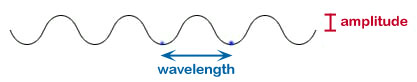
Wavelength (λ): the distance for one complete
vibration. Once you go past one wavelength the pattern starts to
repeat.
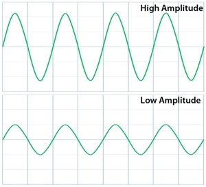
Amplitude (A): the height of the wave above (or below) the rest position. It is related to the energy of the wave. For example, a louder sound will have a greater amplitude. For a transverse wave it will be the height of the wave from its rest position. Crest: high point of a wave Trough: low point of a wave Propagation: the traveling movement of the wave |

|
Phase: The position and direction of a point of a
wave.
Since many waves are sine waves, they can be described using the degrees of a circle. Using A (below) as a starting point: F is 360˚ away from A: it is “in phase” C is 180˚ away from A: it is “out of phase” B is 90˚ out of phase from A |


| 1. Which pairs of points are in phase with each other? 2. Which pairs of points are 180° out of phase of each other? 3. Which points are 90 ° out of phase of E? 4. Which points are 180 ° out of phase of C? 1: BF, DH, CG ; 2: BD, DF, FH, CE, EG ; 3: D & F ; 4:B & D |
| Frequency (f): “how many waves per second” cycles/second or vibrations per second (Hz) Hz = “waves per second” (1/sec) For sound frequency is the pitch Period (T): |
f and Hz are inverses of each other.
|


| 1. Which wave has the largest λ? 2. Which wave has the highest f? 3. Which wave has the highest amplitude? 4. Which waves have the same λ? 1:B ; 2:D ; 3:A ; 4:A&C |
Since waves are usually shown as sine waves, the phase of a wave is
often described in terms of degrees of a circle.
|
The Wave Equation
|
The “wave equation” gives us the relationship between speed, frequency and wavelength: v = fλ(Which I think is one of the prettier equations!) If the velocity of a wave is to stay constant, then the frequency must go up as the wavelength goes down- and vice versa. For example: Light in a vacuum must always be the same speed (c) c = 3.00 x 10⁸m/s If you increase the frequency of the light, say from red light to blue light, then the wavelength must go down. Since f is also equal to 1/T then the equation can be written as v = λ/T(Not as pretty)
Medium: Material through which a wave passes. Mechanical waves such as sound and water waves need a
medium. |
ResonanceResonance: sympathetic vibration Examples of resonance:
InterferenceThe effect of two or more waves passing simultaneously
through the same region of a medium Constructive- two waves that are "in phase" at the same place and same time will add energy to each other making the wave stronger. (Adding +2 and +2) Destructive- two waves that are "out of phase" at the same place and same time will take away energy from each other making the wave weaker. (Adding +2 and -2) Bose ™ noise cancelling headphones. The headphones have a microphone on the outside to pick up outside noise- specifically the steady drone of machines and aircraft engines for example. The sound waves are then reproduced but in the opposite phase to cancel out the noise. Similar to the Bose™ noise cancelling headphones but much cooler! Microphones mounted on the outside of a helicopter pick up the engine and rotor noise. Speakers on the outside of the craft produce the exact sound but, again, 180 º out of phase to cancel out the noise making it almost silent. (This was used on the SEAL Team Six raid into Osama Bin Laden’s stronghold on May 2, 2011.) |


All EM waves move at the speed of light but each type of wave is a different size. We call it a WAVELENGTH .
A WAVELENGTH is the distance from one crest to the crest of the next wave. ( it works with troughs too)
The WAVELENGTH determines the type of light!
FREQUENCY- The number of waves that pass by a fixed point
One wave per second is called 1 Hertz
1,000 waves per second is 1 KiloHertz (AM)
1,000,000 waves per second is 1 MegaHertz (FM)
1,000,000,000 waves per second is 1 GigaHertz (cell phones)
Explore electromagnetic (EM) waves, their features and how they differ from other waves. Learn how EM waves are organized on a spectrum based on the amount of energy they produce, from radio waves to gamma rays.
Heinrich Hertz and Electromagnetic Waves
Who is Heinrich Hertz? If you guessed that he was the founder of the popular
American car rental company with a similar name, you're not alone. But
Heinrich Hertz wasn't a car rental entrepreneur. Instead, he was a German
scientist who performed experiments with electricity when electricity was
still a fancy new thing that scientists had a lot to learn about.
In 1888, when Hertz was 30, he made an electric spark jump from one terminal
to another and noticed a second spark at the same time between two terminals
a couple of yards away. Exciting stuff, I know, but this was 1888, and what
Hertz noticed was a different kind of electromagnetic wave that eventually
came to be known as Hertzian waves.
A few years later, in 1896, a young Italian scientist named Guglielmo
Marconi built on Hertz's discovery and created the first radio transmitter,
sending radio signals for a mile. (A mile!) Hertzian waves are now called
radio waves and are used every day, from listening to the radio to watching
TV.
What Are Electromagnetic Waves?
We are surrounded by waves we can see and hear, from ocean waves to sound
waves. A wave shows the transfer of energy, from the wind that starts an
ocean wave to the sound that moves through the air to your ear drum. Waves
that pass through a physical object or medium are called mechanical waves.
Unlike mechanical waves, electromagnetic waves do not need a medium to
travel or propagate. Electric and magnetic fields both produce vibrations
and, together, the two types of energy create electromagnetic waves.
Waves take different shapes, but electromagnetic waves all have a snake-like
shape, which makes them transverse waves. Transverse waves are measured by
their height, or amplitude, and by their wavelength, or the distance between
the highest point of one wave, the crest, to the crest of the next wave. The
lowest point of a wave is called a trough. Trough to trough can be measured,
too. When analyzing an electromagnetic wave, both the amplitude and distance
between waves is measured.
We measure both the amplitude, or height of a wave (a), and the distance
between waves (b). Diagram of a wavelength

One whole wave, from crest to crest, or trough to trough, is called a cycle.
The number of cycles that occur per second is the wave's frequency. In honor
of Heinrich Hertz, we measure frequency in hertz or Hz.
Types of Electromagnetic Waves
Electromagnetic waves are ordered on the electromagnetic spectrum, by
frequency. They range from radio waves with fewer cycles per second to the
extraordinarily fast and harmful high frequency of gamma rays.

Radio waves have the lowest frequency of the seven bands of waves on the
electromagnetic spectrum, which also means they have the least amount of
energy. Radio waves have wavelengths measuring from miles to the length of a
football, or around 11 inches.
It is common to talk about the frequency of radio waves, or the number of
waves per second. When tuning in to a radio station, a person is listening
to a specific frequency of radio waves. AM stations are numbered from 520 to
1610, with each number representing the frequency of the station at
thousands of hertz per second, or kilohertz, abbreviated kHz. FM station
frequencies range from 87.0 to 107.9 million hertz per second, called
megahertz or MHz.
Sound is converted into EM waves and sent through radio dishes like this one.
Your radio then receives these radio waves and changes them back into sound
waves. Image of a radio satellite
Next on the spectrum are microwaves, a type of radio wave that are less than
11.8 inches long. The microwaves people use to heat food have waves
measuring about five inches. Microwaves aren't just for heating leftovers or
cups of coffee, though. Microwaves are also used for radar, television and
satellites.
Microwaves occur at higher frequencies, with billions or even trillions of
cycles occurring per second. Since writing out 4,000,000 hertz is kind of
clunky, it would be written as 4 gigahertz or 4 GHz. Digital radio is
broadcast at a frequency of 2.5 billion hertz per second, or 2.5 GHz.
Infrared waves occur at an even higher frequency than microwaves. Infrared
waves are used to power television remote controls and for thermal imaging,
like when using a pair of night vision goggles. When you feel warmed by the
sunlight, the energy you feel is infrared radiation from the sun. Since
infrared waves have such high frequencies, their wavelengths are so tiny
they are only hundredths or thousandths of an inch.
All electromagnetic waves are light, but the band of the electromagnetic
spectrum that people and animals can see is called visible light. When a
beam of light passes through a prism, a person can see each color of the
rainbow separated into their individual wavelengths. Red, the longest of the
wavelengths, measures around 700 nanometers; yellow is around 600 nanometers;
and violet, the shortest, is around 400 nanometers in length.
This diagram breaks down the electromagnetic spectrum by frequency and size
of wavelengths. Notice the rainbow-colored section of visible light. Diagram
of the electromagnetic spectrum
Electromagnetic radiation -- electromagnetic spectrum
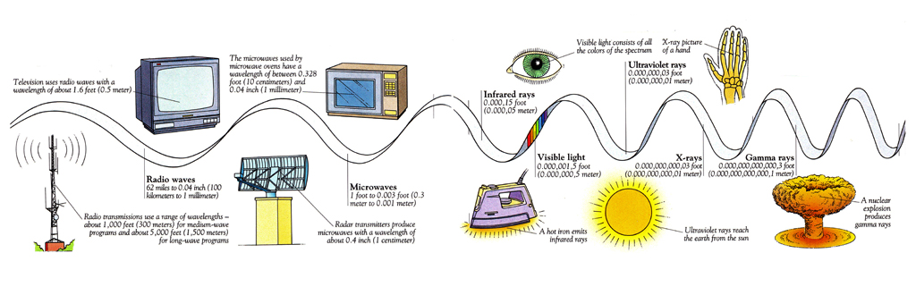
We are bombarded by rays of energy all the time. This is electromagnetic
radiation. Your eyes can detect some of these rays, but most of the
radiation is invisible. Although some are harmful, all of the rays can be
useful to us. They are waves of energy that can travel through space and
matter. Electromagnetic radiation comes from the Sun, stars and galaxies,
traveling through space to reach us. It can also be made artificially. It
consists of electromagnetic waves with a wide range of frequencies and
wavelengths.In order of increasing frequency (or decreasing wavelength),
some of these are: radio waves, microwaves, infrared rays, light rays,
ultraviolet rays, X-rays, and gamma rays. All electromagnetic radiation
travels at the speed of light, and the waves or rays can penetrate materials.
The complete range of frequencies of electromagnetic radiation is the
electromagnetic spectrum.


![]()


Wavelength, amplitude, frequency
The figure below depicts the most important characteristics of an electromagnetic wave: the wave crest and the wave trough. Both undulation conditions, called phases, are repeated periodically. The smallest distance between two points of the same phase, e.g. between two wave troughs, is called the wavelength. The peak of an electromagnetic wave is referred to as its amplitude.
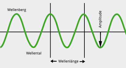

Characteristics of electromagnetic waves.
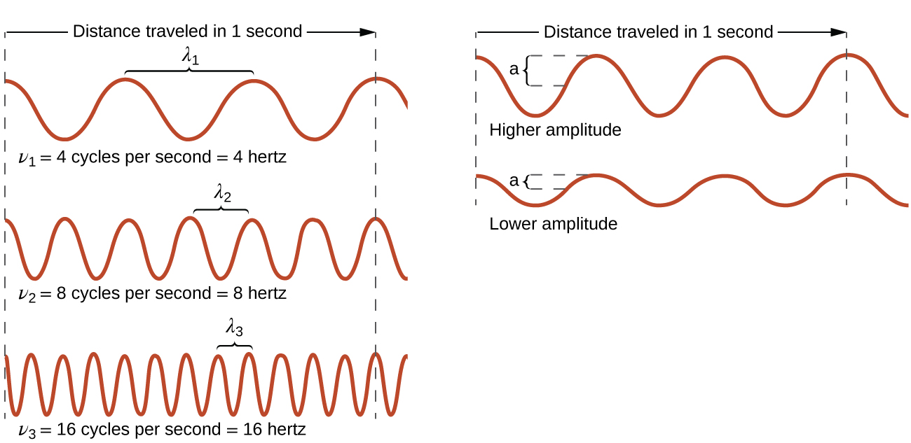
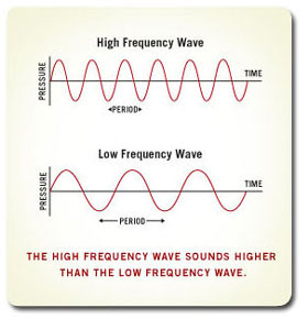
The frequency of wave troughs and wave crests per time unit is called frequency. The shorter a wavelength, the higher the frequency as well as the energy of an electromagnetic wave.

Electromagnetic waves with high and low frequencies.
The electromagnetic spectrum
In nature, there are more kinds of electromagnetic waves such as radio waves and microwaves or the so-called gamma radiation, roentgen (or X-) radiation or thermal radiation. All these waves can be classified within the electromagnetic spectrum according to their wavelengths. For example, radio waves have longer wavelengths than microwaves.

The electromagnetic spectrum arranged according to wavelength ranging from shorter (left) to longer (right) wavelengths.
The image above shows the different waves of the electromagnetic spectrum
according to wavelength ranging from shorter (left) to longer (right)
wavelengths. Leftmost, you can see the short-wavelength and high-energy,
dangerous gamma radiation. In the middle, there is the
visible light and rightmost you can see the long-wavelength
radio waves. Wavelengths range from the size of an atom (several
billionth millimetres) to the size of a city (several kilometres).
If the wavelength of the visible light had to be compared with the diameter of a hair, the hair would have to be split about a hundred times for it to be as extensive as the wavelength of the visible light.
What is Light?

Waves
Light travels in the form of waves. A wave is a traveling disturbance. Examples of waves are waves on a rope and waves in a slinky (recall the demonstrations in class). In the first example the disturbance is the displacement of the rope from its usual position. The pattern of the displacement travels along the rope, but the material that makes up the rope does not go very far. Waves on a rope are called transverse waves because the displacement of the rope is in a direction perpendicular to the direction of propagation of the wave. Similarly, in the second example, the disturbance is the crowding of the rings of the slinky. This disturbance (i.e., the pattern) travels along the slinky while the rings themselves do not go very far away from their usual positions. The wave in the slinky is a longitudinal wave, i.e. the displacement of the rings is in the same direction as the dierection of propagation of the wave. Light resembles waves on a rope: it is a traveling disturbance of the electric and magnetic fields in space. It is thus called an electromgnetic wave. Sound, which is also a wave, resembles waves on a slinky : it has the form of compressions and rarefactions in air.

Here are the main properties of a wave and their significance (see also Fig.2.3. in Ch.2 of the textbook):
Wavelength and Amplitude
| amplitude: | how high are the peaks relative to the valleys |
| wavelength: | distance between peaks |


- In vacuum, light always travels at a speed of: 3 x 10⁵ km/s = 300,000 km/s, which we have encountered before, in Lecture 2. The is the universal speed limit, in the sense that nothing can travel faster than light. The above equation also means that wevelngth and frequency are inversely proportional to each other. In other words, the higher the frequency, the shorter the wavelength has to be so that their product stays the same and equal to teh speed of light. Saying that a wave (or light) has a high frequency is equivalent to saying that it has a short wavelength.

Wave-Particle Duality of Light
Light does not consist of continuous waves (waves that go from their origin to their destination uninterrupted). Rather it consists of wave packets, which can be thought of as small pieces of a wave that travel together in bundles. This property is caled the wave-particle duality of light (and of all electromagnetic waves in general): light behaves both as a wave and as a stream of particles.
Each wave packet is called a photon and it carries a fixed amount of energy, which is proportional to its frequency. Photons are often refered to as particles as well. Putting all of these principles together we can sumarize the relationship between wavelength, frequency, and energy of a photon as follows:
lower energy in a photon = longer wavelength = lower frequency
higher energy in a photon = shorter wavelength = higher frequency
The Significance of the Wavelength/Frequency/Energy: The Electromagnetic spectrum
Photons travel through space, reach our eyes and interact with the atoms there, depositing their energy. The amount of energy they deposit in the atoms in our eyes depends on the wavelengths of the photons and it determines the color we perceive. This is how we see things. Our eyes are sensitive to photons in a very particular range of wavelengths, which is what we call visible light.
Range of wavelengths of visible light (note that 1 cm = 0.01 m = 10-2 m and 1 nm = 10-9 m):
| 400 nm | to | 700 nm |
|
4 x 10⁻⁵ cm |
7 x 10⁻⁵ cm |
|
| 0.00004 cm | 0.00007 cm | |
| blue | red |


You are probably familiar with other types of electromagnetic radiation (i.e., electromagnetic waves) which are not visible to our eyes, such as radio waves, microwaves, infra-red light, ultraviolet light, X-rays, and gamma rays. These types of radiation are very similar to light in nature, with the only difference that they have a different wavelength.


See the illustration of the electromagnetic spectrum in Fig.2.8 in Ch.2. of the textbook.
| Radio Waves: | Very very long wavelength (a few meters). Used for communications. They pass through the atmosphere without being absorbed. |
| Microwaves: | Much longer wavelength than visible light (typically about 10-3 cm). They are absorbed and emitted by molecules in the atmosphere. |
| Infrared Light: | Somewhat longer wavelength than red light. Emitted by objects at room temperature, such as human bodies. Absorbed by water vapor in the Earth's atmosphere. |
| Visible or Optical Light: | Corresponds to the range of wavelengths listed above. Most of the light from the Sun is emitted in the form of visible light. It can pass through the Earth's atmosphere without being absorbed. |
| Ultraviolet Light: | Short wavelength compared to the blue. Causes tanning or sunburn. Dissociates molecules. Causes mutations in living cells. Absorbed by ozone molecules in the upper atmosphere. |
| X-Rays: | Much shorter wavelength than visible light (high energy). Emitted by very hot gases (plasma). Cause mutations in living cells. Absorbed by the upper layers of the Earth's atmosphere. |
| Gamma-Rays: | Even shorter wavelength than X-rays (much higher energy). Indicative of very high energy processes, such as nuclear reactions or energetic particles gyrating in a magnetic field. Cause mutations in living cells. Absorbed by the upper layers of the Earth's atmosphere. |

Measuring
longitudinal and transverse waves
Here we explain the difference between longitudinal and transverse
waves and how we measure the amplitude, wavelength and frequency. The
equation velocity = frequency x wavelength is explained


It was James Clerk Maxwell who showed in the 1800s that light is an electromagnetic wave that travels through space at the speed of light. The frequency of light is related to its wavelength according to
Let's look at an example calculation.

The unit s-1 is so common when talking about waves that it was given the name Hertz. That is, 1 s-1 = 1 Hz. Thus, we would say that light with a wavelength of 436 nm corresponds to a frequency of 6.88 × 10¹⁴ Hertz.
The region from λ ≈ 400-750 nm is visible to the human eye and is therefore called the visible region of the electromagnetic radiation. As we saw in the example above, blue light is near the high frequency limit of our eyes. Red light, with wavelengths near 750 nm are at the low frequency limit of our eyes. Light that contains all frequencies in the visible region will appear as white light.
More generally, the different regions of the electromagnetic spectrum are given different names. Below are the names given to the different regions (frequency ranges) of light according to their frequency range.


![]()


The most basic concepts about a wave are wavelength ( ), frequency (f), velocity (v), and amplitude.
The first three quantities are related by the equation
wave speed = wavelength x frequency
v =
|
| (1) Imagine ocean waves crashing onto the
beach. Think of reasonable numbers for the following:
(a) What is the wavelength of the waves? That is, what do you think is the distance separating the crest of one wave from the crest of the next wave? (b) What is the frequency of the waves? (Hint: use the formula: wave frequency = 1/wave period. If a wave comes once a minute, wave period is 1 minute; if a wave comes once an hour, wave period is 1 hour.) (c) Fiigure out how fast the waves must be traveling. (Calculate v.) |
Waves in What?
The key concepts in this section are:
| (2) The speed of light is 3.00 x 10⁸ m/sec = 3 x 10⁵ km/sec. What is the speed of light in miles/hour? |
Example:
Visible light
Wavelength = l ~ 600 nanometers
     = 6 x 102 x 10-9 meters
     = 6 x 10⁻⁷ m
(1 nanometer = 10-9 meter - TINY!)
So, what is the frequency of visible light?
frequency = speed of light / wavelength
     = 3 x 10⁸ m/s  / 6 x 10⁻⁷ m

     = 0.5 x 10¹⁵ Hz
- yes! VERY high frequency!
Example:
Radio - pick your favorite station! Say, 106 FM
     Frequency = 106 Megahertz ("mega" = 1 million)
     = 1.06 x 102 x 106 Hz
     = 1.06 x 10⁸ Hz
Re-arranging speed of light = wavelength x frquency we can work out the wavelength for radio waves from the 106 FM radio station:
wavelength = speed of light / frequency
     = 3 x 10⁸ m/s  / 1.06 x 10⁸ Hz

     = 3 meters - about 10 feet.
The Electromagnetic Spectrum
The next two figures are very important. Make sure you really understand them.
| (3) The figure above shows the visible part
of the electromagnetic spectrum--the rainbow of colors that is produced
when white light is spread out according to wavelength.
(a) Which has a longer wavelength, blue or red light? (b) Note the units--nanometers (nm)--i.e. 10-9 meter. Green light has a wavelength of 500 nm. How many wavelengths of green light are there in a meter? |
| (4) This next figure (above) shows the
electromagnetic spectrum from gamma rays to radio. Note that the range
of wavelengths covers ten factors of 10, from 10-14 meter to
104 meters (or 10 km).
(a) Infrared radiation is the energy you feel from a fire. The wavlength of infrared light is about 1 "micro-meter" = 1 micron. How many infrared wavelengths are there in a meter? (b) Microwave radiation is easily absorbed by water and allows us to heat up food quickly. How many microwave wavelengths, each 1mm long, are there in a meter? |

We have all seen waves (water waves, flags rippling in the wind, vibrations
along ropes or strings), so we know what they are when we see them. They
are a disturbance propagating though a medium in such a way that the
disturbance moves, but the medium itself does not. Waves come in two
varieties: transverse and longitudinal. For a transverse
wave, the medium vibrates at right angles to the wave motion (example:
waves on a rope). For a longitudinal wave, the medium vibrates in the same
direction as the wave motion (example: waves along a slinky).
Physicists characterize waves by three parameters: amplitude, frequency,
and wavelength. The amplitude is the "height" of the wave, or in other
words, a measure of the energy in the wave. You find the frequency of a
wave by counting how many wave crests pass a fixed point in a certain
interval of time. Frequency is usually measured in cycles per second, also
known as hertz (Hz). (That is, a 100 Hz wave has a frequency of 100 cycles
per second.) The wavelength is the distance from one wave crest to the next.

For sound waves, amplitude is related to the loudness of the sound, and
frequency is related to the pitch. The higher the frequency of the sound
wave, the higher the pitch. The speed of a sound wave through air at room
temperature and pressure is about 343 m/s. You can relate the speed of the
sound wave to its wave parameters by:
v = f l
where: v = the speed of the wave, f = the wave frequency,
l = the wavelength.
For many types of waves, including sound waves, the speed of the wave
through a medium does not depend too much on the frequency. Sound waves of
high frequency and low frequency move at pretty much the same speed through

All waves carry energy and momentum, just like particles. They can interact
with matter, and transfer momentum, and cause heating to occur, and so forth.
Waves have several properties which are distinctly different from those of
particles, however. The most important ones are interference and
diffraction.


What is Wave Frequency?
We know that disturbance causing energy transfer from one point to another
is called a wave. Let us consider a wave traveling from point. So let us
count how many oscillations passes through that point in sometime time say 1
second. This is called the frequency of that wave with respect to that point.
Thus in general, we can say wave frequency is the number of oscillations
made by the wave per unit time. The unit for wave frequency is Hertz or Hz.
Wave Frequency Definition
The Wave frequency is defined as "The total number of vibrations or
oscillations made by the particles per unit time is called the Wave
Frequency and is denoted by f.
The formula for the Wave Frequency is:
f = Number of Oscillation / Time taken
The inverse or the reciprocal of the time period is the frequency of the
wave.
The frequency is the quantity obtained when we divide velocity of the wave
by its wavelength.
f = 1/T
where T = time period.
Frequency Waves
The figure depicts the different types of waves as classified according to
their frequencies.

Formula for Frequency of a Wave
Here are some of the formulas for wave frequency:
If the wave equation is
y = A sin (ωt + ϕ)
where ω = Angular frequency,
ϕ = phase difference,
t = time period.
The frequency is related to angular frequency by the formula:
f = ω2π
The formula for the frequency to the time period in a wave is:
f = 1/T
where T = time period
Angular frequency,
ω= 2 π f = dθ /dt
Unit : Radian Per Second.
Velocity of the wave is related to the frequency by the formula:
f = vλ
where f = frequency,
λ= Wavelength.
if we consider the wave (electromagnetic wave) to be moving through vacuum
then v = c or the speed of light. Hence the formula reduces to:
f = C/λ
Here C = 3 × 10⁸ m/s.
The Frequency of a Wave is?
The total number of vibrational cycle or the oscillations that are made per
second by the particles is called frequency of the wave. or The total number
of distinct cycles that are completed in unit time.
The frequency is dependent on both wavelength and velocity of the wave. The
mathematical relation to wavelength and velocity by the following formula:
V = f .λ
where V = Velocity of the wave,
f = frequency of the wave,
λ= wavelength of the wave.
The Frequency of a Sound Wave Determines?
The total number of complete back-and-forth particle vibrations of the
medium per unit time in sound wave is called the Sound Wave Frequency.
For the sound wave we use Hertz as the unit of measurement where 1 Hertz = 1
vibration/second.
Conceptually whenever a wave passes the medium it makes the first particle
to which it comes in contact, vibrate. Then this particle vibrates the
nearby particle at the same frequency. This is how energy is propagated.
This is clear that the particles vibrate at the same frequency.
Waves can be of two types:
1.High frequency wave
2.Low frequency wave.
In a High frequency wave the numbers of vibrations per unit time are far
more than that of a low frequency wave.
The sound moreover depends on pitch, loudness and quality where pitch is
related to frequency of the sound wave.
Radio Waves Frequency
1.These are the waves which are having the lowest frequency in the
electromagnetic spectrum. They are given out by transmitter.
2.They are formed as a result of thunder, lightning etc.
3.They are used in communication mostly.
4.They are of four types of radio waves namely:
-Long wave
-Medium wave
-Ultra high frequency (UHF)
-Very High frequency (VHF).
The Prolonged exposure to these frequency rays is known to cause cancer.
Applications:
1.They are Used by antennas.
2.They are used for data transmission via modulation.
3.The frequency ranges from 3 KHZ to 3000 GHz. This is also called radio
frequency.
High Frequency Waves
The High frequency waves are the waves with extremely less wave length.They
have a high frequency. Hence they pass through a given point many number of
times every second. These are utilized in communication over long distances.
Ultrasonic waves and gamma waves are the examples of such waves. Greater the
frequency greater would be the pitch.
Applications:
They can be used for communication to moon.
They Can also be used for various other scientific functions and research.
Sine Wave Frequency
Sine wave is a mathematical function. It basically tells us about the smooth
oscillation that is repetitive.
The sine wave is expressed as:
y = A sin (ωt + ϕ)
Here A = amplitude of the sine wave
Φ= phase of the wave
ω= angular frequency of the wave
Also ω= 2 πf
Here f is the frequency of the wave.
How to Calculate Frequency?
Using above formulas we can calculate the frequency. Below are given some
problems on frequency:
Solved Examples
Question 1: Frequency of a wave motion is 250 Hz. what is its time period?
Solution:
Frequency f = 250 Hz.
Time period T = 1/f
= 1/250Hz
= 0.004s.
Question 2: What is the frequency of a wave with a time period of 0.05
seconds?
Solution:
given Time period, T = 0.05 s
The Frequency is given by
f = 1/T
f = 1 / 0.05s
= 20 Hertz.
Frequency, f = 20 Hertz.
Question 3: A Sound wave traveling in air has a wavelength of 1.6 ×
10-2 m. if the Velocity of sound is 320 m/s. Calculate the frequency of the
sound?
Solution:
Wavelength of the sound λ= 1.6 × 10^-2 m,
Velocity of sound (V) = 320 m/s
Velocity of sound is given by V = f. λ
Frequency f = V/λ
= 320m/s / 1.6×10⁻²m
= 320×10^3 / 16s
= 20 ×10^3 Hz
Frequency f = 2 ×10^4 Hz.

Transverse Waves
Electromagnetic waves consist of electric (E) and magnetic (B) fields propagating through space. These fields are orthogonal (at right angles to each other), in phase (reach same peak at same time), and fluctuate perpendicular to the direction of motion.
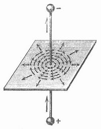
![]()
There you see an EM wave propagating outwardly from a metal rod (antenna) given a high frequency signal. The electric field and current oscillate vertically within the antenna, radiating off a vertically polarized electric field. Because fluctuating electric fields induce fluctuating magnetic fields at right angles and vice versa, electromagnetic waves consist of both coupled together.
An easier way to understand such waves is to visualize them in terms of the vector potential rather than magnetic or electric field. The vector potential is a more fundamental field, analogous to the momentum carried by flowing water. If a thick rope is dragged through water, some of the water surrounding it will be dragged along. Likewise with a wire or antenna through which current flows. The current (I) drags some “ether” along with it, and that flow is the vector potential (A).
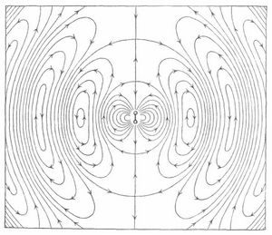
The antenna shown earlier is just a vertical wire with an oscillating rather than steady current. So let’s look at the vector potential field around the antenna:

In this diagram, only a slice of the right side of the field is shown. Here you see the vector potentials varying over distance. If this were animated you would see each arrow oscillate vertically, and the train of these would move out and away from the antenna. The electric field is also oriented vertically since it arises from changes in the vector potential, but with a 90 degree phase lag.
As mentioned earlier, a current-carrying wire is surrounded by a circular magnetic field due to differences between adjacent parts of the vector potential field creating vorticity. Same holds true for the antenna:
Longitudinal Waves
The preceding section depicted electromagnetic waves in terms of the more elementary “vector potential” field. Thinking in terms of fundamental rather than derivative phenomena is the key to understanding almost anything. Here I will use vector potentials to explain longitudinal electromagnetic waves.
To recap, transverse waves are undulations whose orientation of fluctuation is perpendicular to the direction of travel. An antenna given a high frequency electrical signal will radiate a transverse electromagnetic wave. The electric component may be illustrated like so:

The magnetic field is not shown in this diagram but would look similar except being horizontal rather than vertical. Since the electric field derives from changes in the vector potential (A), the wave can be shown in its more fundamental A-field configuration:

The A-field is oriented in the same direction as the E-field but with a phase difference. Notice that there is only one field shown, and that this field is complete in itself; there is no need to draw separate electric and magnetic fields at right angles to each other, because the latter are just two derivative phenomena stemming from this single A-field.
In contrast to transverse waves, longitudinal waves fluctuate in the direction of propagation. A common example would be sound waves, which consist of an alternating series of displacements in air where the displacement points in the direction that sound travels. So for longitudinal EM waves, the vector potential fluctuates in the direction of travel rather than perpendicular to it.


How Antennas Work
We can't see them but radio and television waves are just another form of light. They have a much longer wavelength than visible light but both are electromagnetic radiation.
To generate radio and TV waves we typically make electrons oscillate up and down on an antenna. This is done by applying a variable voltage or alternating current to the antenna. Antennas are generally made of metals and metals act like containers filled with a liquid made of electrons. Metal atoms have one or more weakly held electrons in their outer shells which can "float" from atom to atom.
|
When a negatively charged
electron moves it leaves behind what is generally referred to as a
positively charged hole. The hole is simply an atom with more positive
protons than negative electrons.
The electrical fields for the two types of charges are shown in Figures 1and 2. These are ray diagrams. The arrows show the direction of the force that would be exerted on a unit of positive charge. Unlike a vector diagram, the length of a ray does not indicate the magnitude of the force. Instead, the space between rays indicates magnitude. Both diagrams in Figures 1 and 2 show that the magnitude of the field decreases with increasing distance from the charge because the space between the rays increases. |
|
||||||


We can use a simple analogy to help understand how electromagnetic waves are produced by moving charges. Imagine for a minute that the rays or electric field lines shown in Figures 1 and 2 are like very long springs attached to a circular frame with the charge at the center, almost like a trampoline. If the charge is bounced up and down waves will propagate outward along the springs. Yes, the world of electromagnetic radiation is far more complex than our simple analogy but hopefully it gives you some idea of how a moving charge could create a wave.
| The waves and
variation in the electric field account for the "electro" part of the
term electromagnetic waves.
A moving charge is essentially a current and currents create circular magnetic fields. In Figure 3, a positive charge moving straight out of the page would produce a magnetic field represented by the blue dashed line. The direction of the field can be determined using the right hand thumb rule. The thumb is pointed in the direction of the current and the fingers of the right hand wrapped into a loose fist. The fingers point in the direction of the magnetic field. Note that the magnetic field lines are perpendicular to the electric field lines. This is one of the famous characteristics of electromagnetic waves. |
|
|||

Okay, you're probably wondering why we use an example of a positive charge when we just got finished saying that it's the electrons which move. It turns out that all the conventions in electricity and magnetism are set up for positive charges. Much of this can be traced back to the work of Benjamin Franklin. Unfortunately, the electron had not even been discovered in Franklin's time.
When we talk about current we pretend the positive holes are actually moving in the opposite direction as the electrons. It may seem pretty silly but it does work as a concept and so we're sticking with the tradition.
If a variable voltage is applied, it will send an electrical wave up an antenna. Free electrons in the antenna act as the media for propagating the wave. The situation is similar to longitudinal sound waves propagated in a metal rod. The sound wave is carried by alternating regions of tension and compression. In the compressed areas the rod's molecules are pushed a little closer together. In the tension areas they are pulled a little further apart. Although the molecules barely move, the sound wave can be transmitted great distances.
The very slight motion of electrons up and down an antenna is enough to cause electromagnetic waves to radiate out the sides of the antenna at the same frequency as the variable voltage applied to it. These are used for transmitting radio and television signals as well as other forms of wireless communication.
Like sound, when electrical waves at a defined frequency hit the end of an antenna they are reflected backwards and form a standing wave in the antenna. Antenna waves move at the speed of light (3 x 10 8 m/s) and so the travel time from one end of the antenna to the other is pretty quick.
The electrical waves created on antennas typically have a fixed wavelength. If the length of the antenna is wisely chosen it's possible to make it resonate. The free end of an antenna acts like an open circuit. Voltage drop is maximum across an open circuit and zero across a short circuit. Hence the end of an antenna forms an anti-node or area of maximum voltage or e-field strength. A node is a point which has zero e-field. The distance between an anti-node and node is a quarter of a wavelength.
The wavelength of an electromagnetic wave is calculated as follows:
| l | = |
|
|||
| Where | |||||
| l = wavelength | |||||
| C = speed of light (3 x 10⁸ m/s) | |||||
| f = frequency | |||||
| Figure 4 shows a dipole
antenna which is generally considered the simplest form of antenna. In
this case each half of the antenna is roughly 1/4 wavelength long with
the antenna fed from its center. Hence, the total antenna is 1/2
wavelength long. The ends of the antenna correspond to anti-nodes and
the center to nodes. This configuration causes the antenna to resonate. An antenna will still transmit even if the length is not ideal for resonance. However, less of the power input to the transmitter will actually show up as useful output signal. In other words, the efficiency of the system will be significantly lower. |
|
|||

Dipole antennas are considered balance devices because they are symmetrical and work best when they are fed with a balanced current. In other words, the current has to be of equal size on both halves. This is usually accomplished with a balun when the antenna is fed with a coaxial cable. Coaxial cable is considered unbalanced, hence the word balun is formed from parts of the words BALanced and UNbalanced. A balun is basically a small transformer.
The optimum size of a dipole antenna is slightly different than would be expected based on wavelength alone. This is due to the interaction of the balun and antenna. However, the predicted resonance length is usually very close to the length for optimum broadcast efficiency.
Electromagnetic waves emitted from an antenna are generally modeled as transverse waves. Since the waves have both electric and magnetic field components and are emitted in three dimensional space, the transverse wave model drawn in text books is a bit over simplified but the full picture is almost impossible to draw.
Waves emitted from simple monopole and dipole antennas tend to be polarized. In other words, if the emitting antenna is vertical the receiving antenna also has to be vertical for best reception. If the receiving antenna is horizontal the signal it picks up will be greatly attenuated.
Antenna design is very complex and requires a lot of time and study to master. However, any antenna will have to oscillate charged particles in order to transmit radio signals and will tend to do this best if the antenna is resonating.

Electromagnetic radiation is described as a cyclic repeating wave having
electrical and magnetic fields with amplitude (peak value from the average)
and period (time between repeating portions of the wave). Frequency equals
the number of cycles per second, and the wavelength is the distance between
repeating points as determined from the frequency and velocity (see text for
relationship between velocity, wavelength, and frequency).


Path of EM wave propagation in a circuit wire
The image is my visualization of drift velocity and electromagnetic (EM)
propagation of charge wave in a closed circuit. The slow drift velocity of
the electrons follows the path of the circuit (a circle wire). Does the the
EM wave follow the same path of that of the drift velocity?
Since textbooks and online resources I found offer no understandable
description/differentiation, I assume they take the same path (of the
circuit wire).
But I cannot understand why:
(1) If the wave is induced by and propagation from the voltage source (battery),
then it should take the vector path of the magnetic field created by the
battery, instead of the circuit path.
(2) If the electromagnetic wave is caused by some ballistic effect (electron
“pressuring” the next electron like water molecules in a tube), then
shouldn’t the wave left tangent to the wire and shoot to outer space? (similar
in sound wave, when

To rephrase my question with a better picture, when the battery apply a
electric potential to an closed circuit wire, there are two currents - the
very slow drift current from electrons, and the current in form of EM wave
traveling near the speed of light. What is causing the EM wave the bend and
turn along the wire?
Perhaps I should elaborate that I am not asking about the radiation or
antenna effect. I am curious on the actual "electricity/energy/signal"
current (not the drift current by electrons) going in the path of the
circuit wire instead of radiating outwards. I have amend the picture so it
looks more like a current going through a bulb rather than looking like an
antenna. (sorry for the bad drawing..I did my best job)

Introduction to EM Wave Propagation
Antenna is a set of conducting wires that allow electric current to pass.
When the electric current fluctuates, the lectromagnetic wave radiation
occurs. The antenna radiates the wave energy into space or receive energy
from the space.
The radiation ability depends the wire’s length and shape. For example, if
the two wires are very close, the electric and magnetic field are trapped
between them and the radiation is very weak (figure 1a). As the two wires
are apart further, the radiation becomes stronger, meaning more energy is
radiated into the space (figure1b, figure1c)

The Discovery of Radio Waves - 1888
Heinrich Rudolf Hertz
(1857-1894)
Heinrich Hertz was the first to send and receive radio waves. James Clerk Maxwell had mathematically predicted their existence in 1864. Between 1885 and 1889, as a professor of physics at Karlsruhe Polytechnic, he produced electromagnetic waves in the laboratory and measured their wavelength and velocity. He showed that the nature of their reflection and refraction was the same as those of light, confirming that light waves are electromagnetic radiation obeying the Maxwell equations.
All of these findings were first published in the journal Annalen der Physik,(see below right) then in Hertz's first book, Untersuchungen Ueber Die Ausbreitung Der Elektrischen Kraft (Investigations on the Propagation of Electrical Energy), shown at right. His book is considered to be one of the most important works of science. This is where he first describes his confirmation of the existence of electromagnetic waves.
Annalen der Physik und Chemie is one of the oldest physics journals worldwide. The journal, still in publication today, publishes original papers in the areas of experimental, theoretical, applied and mathematical physics and related areas.
Hertz's Experiment:
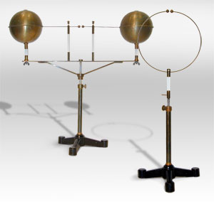

Early experimental Hertz
radiator and resonator for creating and detecting Hertzian waves
~1890
Simple spark gap apparatus similar to this was the first ever built to
produce and detect radio waves
There are 12 complete volumes of Annalen der Physik und Chemie in my collection. Included are Hertz's many papers proving the Maxwell hypothesis on the propagation of electromagnetic waves. These papers laid the foundation for the development of radio and electromagnetic wave transmission applications. Also included are more Hertz papers plus others by Roentgen, Planck, Boltzmann, Angstrom, Helmholtz.
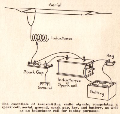

Rádio sparkgap
Hertz's electric-wave generator consisted of a spark gap to which
was attached a pair of outwardly extending conductors, corresponding in a
miniature way to the aerial and earth wires of a modern radio transmitter.
His receiver was a wire ring having a minute opening across which, when
electro-magnetic waves arrived, tiny sparks would pass. This wire ring was
in some respects like the loop receiver of today; with it Hertz was able not
only to indicate the receipt of waves, but also to determine their intensity
and direction of travel. Heinrich Hertz, despite the fact that his work was
limited to laboratory distances and that he did not suggest the use of his
waves for telegraphy, is the pioneer whose experiments laid the foundation
for radio as we now know it.
A few years after Hertz's first work with invisible electro-magnetic waves,
Elihu Thomson, of Lynn, Massachusetts, proposed (1889) their use for
signaling through fogs or even through solid bodies that would shut off
light waves. Sir William Crookes in 1892 made a startling prophecy of
electric-wave telegraphy and telephony. Meanwhile, Hertz's experiments had
been taken up and extended by a number of scientists, chief among whom were
Professor Edouard Branly, of Paris; Sir Oliver Lodge, of London; and
Professor Augusto Righi, of Bologna, Italy. Branly and Lodge devised
numerous forms of “radio conductors”, or receivers utilizing some of the
phenomena also discovered by Hughes, for the delicate reception of electric
waves; Righi invented various types of wave producers and con-firmed and
added to Hertz's observations.


Calculate the theoretical length for a "half-wave" antenna, assuming a transmitter "carrier" frequency of 105.3 MHz:

Shown here is a simple quarter-wave antenna, comprised of a single wire projecting vertically from one terminal of an RF voltage source, the other terminal connected to earth ground:
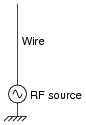
We know at this point that any circuit comprised of inductance (L) and capacitance (C) is capable of resonating: attaining large values of AC voltage and current if ëxcited" at the proper frequency. The so-called tank circuit is the simplest example of this:


A spark-gap transmitter for generating radio frequency electromagnetic waves. Such devices served as the transmitters for most early wireless systems.

Electro-magnetic waves wireless transmission and reception system in the beginning of XX century. The spark gap in the induction coil can be switched on and off by a telegraphic key. Oscillatory currents from the spark gap excite the coherer, which becomes conductive. When the coherer is placed in series with a battery and a telephone receiver, it switch the currents on and off in synchronization with the telegraphic key in the transmitter.

a) Telegraphic key
b) Spark gap
c) Coherer
d) Telegraphic receiver
e) Telephone receiver
![]()
Spark gap transmitter

For example, in the case of the nuclear power plant, the receptor was readily identified. The turbine control valves were malfunctioning. The source and the coupling path were originally unknown; however an investigation revealed that wireless handsets used by the plant employees were the source. Although at this point the coupling path was not known, the problem was solved by eliminating the source (e.g. restricting the use of low‑power radio transmitters in certain areas). A more thorough and perhaps more secure approach would be to identify the coupling path and take steps to eliminate it. For example, suppose it was determined that radiated emissions from a wireless handset were inducing currents on a cable that was connected to a printed circuit card that contained a circuit that controlled the turbine valves. If the operation of the circuit was found to be adversely affected by these induced currents, a possible coupling path would be identified. Shielding, filtering, or rerouting the cable, and filtering or redesigning the circuit would then be possible methods of attenuating the coupling path to the point where the problem is non‑existent.
The source of the tramway problem was thought to be transients on the tramway's power. The coupling path was presumably through the power supply to the speed control circuit, although investigators were unable to reproduce the failure so the source and coupling path were never identified conclusively. The receptor, on the other hand, was clearly shown to be the speed control circuit and this circuit was modified to keep it from becoming confused by unintentional random inputs. In other words, the solution was to eliminate the receptor by making the speed control circuit immune to the electromagnetic phenomenon produced by the source.
Potential sources of electromagnetic compatibility problems include radio transmitters, power lines, electronic circuits, lightning, lamp dimmers, electric motors, arc welders, solar flares and just about anything that utilizes or creates electromagnetic energy. Potential receptors include radio receivers, electronic circuits, appliances, people, and just about anything that utilizes or can detect electromagnetic energy.
Methods of coupling electromagnetic energy from a source to a receptor fall into one of four categories.
- Conducted (electric current)
- Inductively coupled (magnetic field)
- Capacitively coupled (electric field)
- Radiated (electromagnetic field)
Coupling paths often utilize a complex combination of these methods making the path difficult to identify even when the source and receptor are known. There may be multiple coupling paths and steps taken to attenuate one path may enhance another.
A Brief History of EMC
In the late 1880's, the German physicist Heinrich Hertz performed
experiments that demonstrated the phenomenon of radio wave propagation, thus
confirming the theory published by James Clerk Maxwell two decades earlier.
Hertz developed a spark in a small gap between two metal rods that were
connected at the other end to metal plates as shown in Figure 2. The spark
excitation created an oscillating current on the rods resulting in
electromagnetic radiation near the resonant frequency of the antenna. The
receiving antenna was a loop of wire with a very thin gap. A spark in the
gap indicated the presence of a time‑varying field and the maximum spark gap
length provided a measurement of the received field's strength.

Figure 2. Early antennas constructed by Heinrich Hertz.
Guglielmo Marconi learned of Hertz's experiments and improved upon them. In
1895, he developed the wireless telegraph, the first communications device
to convey information using radio waves. Although the significance of his
invention was not initially appreciated, the U.S. Navy took an interest due
to the potential of this device to enhance communication with ships at sea.
In 1899, the Navy initiated the first shipboard tests of the wireless
telegraph. While the tests were successful in many ways, the Navy was unable
to operate two transmitters simultaneously. The reason for this problem was
that the operating frequency and bandwidth of the early wireless telegraph
was primarily determined by the size, shape and construction of the antenna.
Receiving antennas were always "tuned" (experimentally) to the same
operating frequency as the transmitting antenna, however the bandwidth was
difficult to control. Therefore when two transmitters were operating
simultaneously, receivers detected the fields from both of them to some
extent and the received signal was generally unintelligible. This early
electromagnetic compatibility problem came to be referred to as Radio
Frequency Interference (RFI). As the popularity of the wireless telegraph
grew, so did the concern about RFI.
In 1904, Theodore Roosevelt signed an executive order empowering the
Department of Commerce to regulate all private radio stations and the Navy
to regulate all government stations (and all radio stations in times of war).
Different types of radio transmitters were assigned different frequency
allocations and often were only allowed to operate at certain times in order
to reduce the potential for RFI.
By 1906, various spark‑quenching schemes and tuning circuits were being
employed to reduce the bandwidth of wireless transmitters and receivers
significantly. However, it was the invention of the vacuum tube oscillator
in 1912 and the super heterodyne receiver in 1918 that made truly narrow
band transmission and reception possible. These developments also made it
possible to transmit reasonably clear human speech, which paved the way for
commercial radio broadcasts.
The period from about 1925 to 1950 is known as the golden age of
broadcasting. During this period the popularity of radio soared. As the
number of radios proliferated, so did the electromagnetic compatibility
problems. RFI was a common problem because the regulations governing
intentional or unintentional interference with a commercial radio broadcast
were lax and more people had access to radio equipment. In order to
alleviate this problem, the Federal Communications Commission (FCC) was
established in 1934 as an independent agency of the U.S. Government. It was
empowered to regulate U.S. interstate and foreign communication by radio,
wire, and cable. FCC regulations and licensing requirements significantly
reduced the number of radio frequency interference problems.
However, due to the increasing number of radio receivers being located in
homes, the general public was introduced to a variety of new EMC problems.
Unintentional electromagnetic radiation sources such as thunderstorms,
gasoline engines, and electric appliances often created bigger interference
problems than intentional radio transmitters.
Intrasystem interference was also a growing concern. Super heterodyne
receivers contain their own local oscillator, which had to be isolated from
other parts of the radio's own circuit. Radios and phonographs were lumped
together in home entertainment systems. Radios were installed in automobiles,
elevators, tractors, and airplanes. The developers and manufacturers of
these systems found it necessary to develop better grounding, shielding, and
filtering techniques in order to make their products function.
In the 1940's many new types of radio transmitters and receivers were
developed for use during World War II. Radio signals were not only used for
communication, but also to locate ships and planes (RADAR) and to jam enemy
radio communications. Because of the immediate need, this equipment was
hurriedly installed on ships and planes resulting in severe EMC problems.
Experiences with electromagnetic compatibility problems during the war
prompted the development of the first joint Army‑Navy RFI standard, JAN‑I‑225,
"Radio Interference Measurement," published in 1945. Much more attention was
devoted to RFI problems in general, and techniques for grounding, shielding
and filtering in particular. Electromagnetic compatibility became an
engineering specialization in a manner similar to antenna design or
communications theory.
In 1954, the first Armour Research Foundation Conference on Radio Frequency
Interference was held. This annual conference was sponsored by both
government and industry. Three years later, the Professional Group on Radio
Frequency Interference was established as the newest of several professional
groups of the Institute of Radio Engineers. Today, this group is known as
the Electromagnetic Compatibility Society of the Institute of Electrical and
Electronics Engineers (IEEE).
During the 1960's, electronic devices and systems became an increasingly
important part of our society and were crucial to our national defense. A
typical aircraft carrier, for example, employed 35 radio transmitters, 56
radio receivers, 5 radars, 7 navigational aid systems, and well over 100
antennas [1]. During the Vietnam War, Navy ships were often forced to shut
down critical systems in order to allow other systems to function. This
alarming situation focused even more attention on the issue of
electromagnetic compatibility. Outside the military, an increasing
dependence on computers, satellites, telephones, radio and television made
potential susceptibility to electromagnetic phenomena a very serious concern.
The 1970's witnessed the development of the microprocessor and the
proliferation of small, low‑cost, low‑power semiconductor devices. Circuits
utilizing these devices were much more sensitive to weak electromagnetic
fields than the older vacuum tube circuits. As a result, more attention was
directed toward solving an increasing number of electromagnetic
susceptibility problems that occurred with these circuits.
In addition to traditional radiated electromagnetic susceptibility (RES)
problems due to intentional and unintentional radio frequency transmitters,
three additional classes of electromagnetic susceptibility problems gained
prominence in the '70s. Perhaps the most familiar of these, outside the
military, is electrostatic discharge (ESD). An electrostatic discharge
occurs whenever two objects with a significantly different electric
potential come together. The "shock" that is felt when a person reaches for
a door knob after walking across a carpet on a dry day is a common example.
Even discharges too weak to be felt however, are capable of destroying
semiconductor devices.
Another electromagnetic susceptibility problem that gained notoriety during
the '70s was referred to as EMP or ElectroMagnetic Pulse. The military
realized that a high‑altitude detonation of a nuclear warhead would generate
an extremely intense pulse of electromagnetic energy over a very wide area.
This pulse could easily damage or disable critical electronic systems. To
address this concern, a significant effort was initiated to develop
shielding and surge protection techniques that would protect critical
systems in this very severe environment.
The emergence of a third electromagnetic susceptibility problem, power line
transient susceptibility (PLT), was also a direct consequence of the
increased use of semiconductor devices. Vacuum tube circuits generally
required huge power supplies that tended to isolate the electronics from
noise on the power line. High‑speed, low‑power semiconductor devices on the
other hand were much more sensitive to transients and their modest power
requirements often resulted in the use of relatively small low‑cost supplies
that did not provide much isolation from the power line. In addition, the
low cost of these devices meant that more of them were being located in
homes and offices where the power distribution is generally not well
regulated and relatively noisy.
The emphasis on electromagnetic susceptibility during the 1970's is
exemplified by the number of task groups, test procedures, and product
standards dealing with susceptibility that emerged during this decade. One
organization established in the late 70's known as the EOS/ESD Association (EOS
stands for Electrical Over Stress) deals exclusively with the susceptibility
problems mentioned above.
Another change that occurred during the 60's and 70's was the gradual
displacement of the term RFI by the more general term EMI or Electromagnetic
Interference. Since not all interference problems occurred at radio
frequencies, this was considered to be a more descriptive nomenclature. EMI
is often categorized as radiated EMI or conducted EMI depending on the
coupling path.
Two events in the 1980's had significant, wide‑ranging effects on the field
of electromagnetic compatibility.
The introduction and proliferation of low priced personal computers and
workstations.
Revisions to Part 15 of the FCC Rules and Regulations that placed limits on
the electromagnetic emissions from computing devices.
The proliferation of low priced computers was important for two reasons.
First, a large number of consumers and manufacturers were introduced to a
product that was both a significant source and receptor of electromagnetic
compatibility problems. Secondly, the availability of low cost, high speed
computation spurred the development of a variety of numerical analysis
techniques that have had an overwhelming influence on the ability of
engineers to analyze and solve EMC problems.
The FCC regulations governing EMI from computing devices were phased in
between 1980 and 1982. They required all electronic devices operating at
frequencies of 9 kHz or greater and employing "digital techniques" to meet
stringent limits regulating the electromagnetic emissions radiated by the
device or coupled to the power lines. Virtually all computers and computer
peripherals sold or advertised for sale in the U.S. have to meet these
requirements. Many other countries established similar requirements.
In the 1990's, the European Union adopted EMC regulations that went well
beyond the FCC requirements. The European regulations limited unintentional
emissions from appliances, medical equipment and a wide variety of
electronic devices that were exempt from the FCC requirements. In addition,
the European Union established requirements for the electromagnetic immunity
of these devices and defined procedures for testing the susceptibility of
electronic systems to radiated electromagnetic fields, conducted power and
signal line noise, and electrostatic discharge.
The impact of these regulations was overwhelming because for the first time
engineers, managers, and corporate presidents were made painfully aware of
what it means to have an EMC problem. At a time when the market for
computers was mushrooming, many of the latest, most advanced designs were
being held back because they were unable to meet government EMI requirements.
Companies formed EMC departments and advertised for EMC engineers. An entire
industry emerged to supply shielding materials, ferrites, and filters to
computer companies. EMC short courses, test labs, magazines, and consultants
began appearing throughout the world. The international attention focused on
EMC encouraged additional research. Significant progress was made toward the
development of more comprehensive test procedures and meaningful standards.
Today these trends are continuing. Computing devices are getting denser,
faster, and more complex creating new challenges for the EMC engineer while
advances in numerical electromagnetics are revolutionizing the state‑of‑the‑art
in EMC analysis. Regulations limiting electromagnetic emissions continue to
be upgraded and new regulations concerning the susceptibility of electronic
devices are being developed and introduced.
The Future of Electromagnetic Compatibility
If you were to listen to a computer company executive explaining corporate
strategy for dealing with EMC problems in the future, you would very likely
hear something like "We are striving to make EMC an integral part of the
product design process, rather than attempting to solve problems by 'patching'
a design that is nearly complete." Of course this is not a new idea. Since
the early RFI problems with the wireless telegraph, engineers have realized
that it is cheaper, easier and more effective to design a product that is
compatible than it is to "fix" an existing design that has an EMC problem.
To some extent, early EMC involvement has been a goal all along and steady
progress has been made.
For example, radio circuit designers are keenly aware of bandwidth
requirements and out‑of‑band radiation is rarely a problem anymore even with
prototype designs. When digital circuits first appeared, interference
between the digital and analog portions of a device was common, however
eventually this became less of a problem as circuit designers learned to
isolate analog and digital grounds. Today, computers are routinely designed
with some degree of shielding, filtering, and special grounding techniques.
The reason that "early EMC involvement" continues to be extolled as an idea
whose time has come is that the scope and complexity of EMC problems is
steadily increasing. New technologies create unique situations rendering
existing EMC "fixes" and design rules obsolete. Engineers who are familiar
with fundamental EMC concepts and analysis techniques can readily apply this
knowledge to emerging technologies and anticipate potential EMC problems
during a product's design phase. In the past however, the emphasis has been
on communicating the design rules and fixes themselves rather than "burdening"
the circuit designers with fundamental EMC concepts. As a result, EMC
problems have kept one step ahead of the circuit designers and the call for
"early EMC involvement" continues.
Fortunately, this situation is beginning to change. The tips and tricks that
caused many engineers to view EMC as a black art are being examined more
closely and used with greater caution. More significantly, the importance of
many fundamental principles drawn from electromagnetics and circuit theory
is being recognized. These principles are essential to an understanding of
how a circuit interacts with its electromagnetic environment.
In the years to come, as EMC continues to evolve from an engineering art to
an engineering science, the need to make the principles of EMC part of the
electrical engineering curriculum will become more apparent. Advances in
computer hardware and numerical modeling techniques will enable the
efficient application of these principles to the analysis of complex
circuits and systems. Once circuit and system designers are familiar with
these concepts and techniques, "early EMC involvement" will be the rule
rather than just the goal.
Electric Field
Around every electrically charged object is a force field that can be detected and measured. This force field can cause electric charges to move in the field. When an object is charged electrically, there is either a greater or a smaller concentration of electrons than normal. Thus, a difference of potential exists between a charged object and an uncharged object. An electric field is, therefore, associated with a difference of potential, or a voltage.
This invisible field of force is commonly represented by lines that are drawn to show the paths along which the force acts. The lines representing the electric field are drawn in the direction that a single positive charge would normally move under the influence of that field. A large electric force is shown by a large concentration of lines; a weak force is indicated by a few lines.
When a capacitor is connected across a source of voltage, such as a battery, it is charged by a particular amount, depending on the voltage and the value of capacitance. (See figure 1-25.) Because of the emf (electromotive force) of the battery, negative charges flow to the lower plate, leaving the upper plate positively charged. Along with the growth of charge, the electric field is also building up. The flux lines are directed from the positive to the negative charges and at right angles to the plates. When the capacitor is fully charged, the voltage of the capacitor is equal to the voltage of the source and opposite in polarity. The charged capacitor stores the energy in the form of an electric field. It can be said, therefore, that an electric field indicates voltage.
Figure 1-25. - Electric fields between plates.
If the two plates of the capacitor are spread farther apart, the electric field must curve to meet the plates at right angles (fig. 1-26). The straight lines in view A of figure 1-26 become arcs in view B, and approximately semicircles in view C, where the plates are in a straight line. Instead of flat metal plates, as in the capacitor, the two elements can take the form of metal rods or wires and form the basic antenna.
Figure 1-26. - Electric fields between plates at different angles.
In figure 1-27, two rods replace the plates of the capacitor, and the battery is replaced by an ac source generating a 60-hertz signal. On the positive alternation of the 60-hertz generator, the electric field extends from the positively charged rod to the negatively charged rod, as shown. On the negative alternation, the charge is reversed. The previous explanation of electrons moving from one plate to the other of the capacitor in figure 1-25 can also be applied to the rods in figure 1-27.
Figure 1-27. - Electric fields between elements.
The polarity of charges and the direction of the electric fields will reverse polarity and direction periodically at the frequency of the voltage source. The electric field will build up from zero to maximum in one direction and then collapse back to zero. Next, the field will build up to maximum in the opposite direction and then collapse back to zero. This complete reversal occurs during a single cycle of the source voltage. The HALF-WAVE DIPOLE ANTENNA (two separate rods in line as illustrated in figure 1-27) is the fundamental element normally used as a starting point of reference in any discussion concerning the radiation of electromagnetic energy into space. If rf energy from the ac generator (or transmitter) is supplied to the element of an antenna, the voltage across the antenna lags the current by 90 degrees. The antenna acts as if it were a capacitor.
Magnetic Field
When current flows through a conductor, a magnetic field is set up in the area surrounding the conductor. In fact, any moving electrical charge will create a magnetic field. The magnetic field is a region in space where a magnetic force can be detected and measured. There are two other fields involved - an INDUCTION FIELD, which exists close to the conductor carrying the current, and the RADIATION FIELD, which becomes detached from the current-carrying rod and travels through space.
To represent the magnetic field, lines of force are again used to illustrate the energy. Magnetic lines are not drawn between the rods, nor between high- and low-potential points, as the E lines that were discussed earlier. Magnetic lines are created by the flow of current rather than the force of voltage. The magnetic lines of force, therefore, are drawn at right angles to the direction of current flow.
The magnetic fields that are set up around two parallel rods, as shown in figure 1-28 view A, are in maximum opposition. Rod 1 contains a current flowing from the generator, while rod 2 contains a current flowing toward the generator. As a result, the direction of the magnetic field surrounding rod 1 is opposite the direction of the magnetic field surrounding rod 2. This will cause cancellation of part or all of both magnetic fields with a resultant decrease in radiation of the electromagnetic energy. View B illustrates the fact that if the far ends of rods 1 and 2 are separated from each other while the rods are still connected to the generator at the near ends, more space, and consequently less opposition, will occur between the magnetic fields of the two rods. View C illustrates the fact that placing the rods in line makes the currents through both rods flow in the same direction. Therefore, the two magnetic fields are in the same direction; thus, maximum electromagnetic radiation into space can be obtained.
Figure 1-28. - Magnetic fields around elements.
Magnetic lines of force are indicated by the letter H and are called H lines. The direction of the magnetic lines may be determined by use of the left-hand rule for a conductor: If you grasp the conductor in your left hand with the thumb extended in the direction of the current flow, your fingers will point in the direction of the magnetic lines of force. In view C of figure 1-28, the direction of current flow is upward along both halves of the elements (conductors). The lines of magnetic force (flux) form concentric loops that are perpendicular to the direction of current flow. The arrowheads on the loops indicate the direction of the field. The left-hand rule is used to determine the direction of the magnetic field and is illustrated in figure 1-29. If the thumb of the left hand is extended in the direction of current flow and the fingers clenched, then the rough circles formed by the fingers indicate the direction of the magnetic field.
Figure 1-29. - Left-hand rule for conducting elements.
Q.46 What do we call the field that is created between two rods when a
voltage is applied to them?
Q.47 When current flows through a conductor, a field is created around the
conductor. What do we call this field?
![]()
Simple Marconi Radiator. (Transmitter ) (Left Picture) = B, battery; I, induction coil; K, signaling key; S, spark gap; A, aerial wire; E, earth plate.
![]()
|
|
|
THE APPARATUS FOR WIRELESS TELEGRAPHY.


With this apparatus Heinrich Hertz proved that an electric spark produced impulses which travel through the air. A spark leaped across contacts on the left, inducing current in the ring on the right.
![]()


“Swift as wireless message my wishes rush through space to greet you”. These were the very words from the discoverer of the modern wireless communication—–Marconi, Guglielmo. It was a spark on how the wireless communication had been born to this world, and like a blink on how it is able to grow. However, this would become impossible for us without the people who contributed their ideas to the concept of so called “wireless communication”. So as we venture to our yesterday’s yesterdays, just relax and enjoy.
From time to time, the discovery of “wireless communication” ignited from the past years.
From Telegraph to “The Birth of Radio”, 1867-1896
- 1867 — Maxwell predicts existence of electromagnetic (EM) waves
- 1886 – A German physicist, Heinrich Hertz performed an experiment which made a way to the revolutionized communication. His experiment consists of two circuits with a small gap. When he connected it to the high voltage source, a spark occurred even without contact. Somehow energy from the first spark was received by the second circuit. This energy was carried through EM waves or Electromagnetic waves.

Figure 1.1 — Hertz experiment, consisting of a transmitter (1) and a
receiver (2)
- 1887 — Hertz proves existence of EM waves; first spark transmitter generates a spark in a receiver several meters away
- 1890 — Branly develops coherer for detecting radio waves
- 1896 — Guglielmo Marconi demonstrates wireless telegraph to English telegraph office
“The Birth of Radio”
- 1895 – Hertz didn’t think that this is a new means of transmitting information without wires attached that’s why Guglielmo Marconi opened the way for modern wireless communications by transmitting the three-dot Morse code for the letter ‘S’ over a distance of three kilometers using electromagnetic waves. From this beginning, wireless communications has developed into a key element of modern society. From satellite transmission, radio and television broadcasting to the now ubiquitous mobile telephone, wireless communications has revolutionized the way societies function.
- 1897 — “The Birth of Radio” – Marconi awarded patent for wireless telegraph
- 1897 — First “Marconi station” established on Needles island to communicate with English coast
- 1898 — Marconi awarded English patent no. 7777 for tuned communication
- 1898 — Wireless telegraphic connection between England and France established
For an LC circuit, frequency 1/2π √LC. Since L and C are quite small, the frequency of oscillation is very high = 100Mhz. Em waves are radiated at this frequency as a result of the oscillation (and hence acceleration) of free charges in the loop. Hertz was able to detect these waves using a single loop of wire with its own spark gap (the receiver) this loop, placed several meters from the transmitter, has its own effective inductance, capacitance, and natural frequency of oscillation. Sparks were induced across the gap of the receiving electrodes when the frequency of the receiver was adjusted to match that of the transmitter. Thus, Hertz demonstrated that the oscillating current induced in the receiver was produced by em waves radiated by the transmitter.

MAXWELL’S WAVES DISCOVERED
In 1865 James Clerk Maxwell predicted the existence of electromagnetic waves.
He suggested that an accelerated charge would produce a non-uniformly
changing electric field that would in turn produce a changing magnetic field.
By Faraday’s Law, this non-uniformly changing magnetic field would in turn
produce a changing electric field and so on. He showed mathematically that
such fields would propagate through space as a wave motion with a speed of 3
x 108 m/s. This speed agreed so closely with values of the speed of light
measured by Fizeau in 1849 and Foucault in 1862 that Maxwell became
convinced that light was a form of electromagnetic wave.
Heinrich Hertz, a German physicist, achieved the first experimental
demonstration of electromagnetic waves in 1887. Hertz used an induction coil
to produce oscillating electric sparks between two brass balls connected to
two brass plates. The brass plates acted as an aerial system. He used a
small loop of wire with a tiny gap in it as the receiver. See diagram below.

As sparks jumped across the gap between the balls, sparks were also observed
jumping the gap in the receiver. Hertz reasoned that the spark discharge
oscillating backwards and forwards between the brass balls set up changing
electric and magnetic fields that propagated as an electromagnetic wave, as
postulated by Maxwell. When these waves arrived at the receiver, the
changing electric field component caused charges in the loop to oscillate,
thus producing the spark across the gap in the receiver.
Hertz carried out a thorough investigation of these waves and showed that
they did indeed possess properties similar to light – reflection, refraction,
interference, diffraction and polarisation. By setting up an experiment in
which he allowed the waves to reflect from a metal sheet and interfere with
themselves to produce standing waves, Hertz was able to determine their
wavelength. He calculated the frequency of oscillation of the sparks in his
transmitter from knowledge of the parameters of the circuit. Then using
v = f l
he calculated the speed of the waves as 3 x 10⁸ m/s, as predicted by Maxwell.
Thus, Hertz’s experiment confirmed Maxwell’s prediction of EM waves and
provided strong experimental support for the idea that light was a form of
transverse EM wave.
The waves produced by Hertz eventually became known as radio waves and his
research led to the development of radio communications. As Hertz suspected
it was indeed oscillating charges that produced the EM waves. Today we know
that radio waves are produced when an oscillating voltage applied to an
antenna causes free electrons to oscillate along that antenna. This
generates an EM wave that spreads out from the transmitter at 3 x 10⁸ m/s.
When the EM wave strikes a receiving antenna it forces charges in the
antenna to oscillate at the frequency of the wave. This oscillating
electrical signal is then converted into an audio-frequency signal by diodes
in appropriately tuned electronic circuits.
Applications of the production of EM waves by oscillating electric charges
in radio antennae started with the demonstration of “wireless” telegraphy by
Sir Oliver Lodge in 1894. Marconi accomplished the first trans-Atlantic
transmission in 1901. The invention of the triode valve amplifier in 1906
enabled radio transmission of speech and music over long distances. The
invention of the transistor in 1948 eventually resulted in further
improvements in radio transmission and reception and decrease in size of
transmitters and receivers. Today, radio communications networks, citizen-band
radio, mobile phone networks and television image transmission are examples
of applications of EM wave production. (This information in this last
paragraph is no longer required by the Syllabus.)
The Discovery of Electromagnetic Radiation
The most dramatic prediction of Maxwell's theory of electromagnetism,
published in 1865, was the existence of electromagnetic waves moving at the
speed of light, and the conclusion that light itself was just such a wave.
This challenged experimentalists to generate and detect electromagnetic
radiation using some form of electrical apparatus.
The first clearly successful attempt was made by Heinrich Hertz in 1886. For
his radio wave transmitter he used a high voltage induction coil, a
condenser (capacitor, Leyden jar) and a spark gap - whose poles on either
side are formed by spheres of 2 cm radius - to cause a spark discharge
between the spark gap’s poles oscillating at a frequency determined by the
values of the capacitor and the induction coil.
This first radio waves transmitter is basically, what we call today, an LC
oscillator. For an animated explanation of this device click here. More
information about this subject could be found in basic electronics text
books.
To prove there really was radiation emitted, it had to be detected. Hertz
used a piece of copper wire, 1 mm thick, bent into a circle of a diameter of
7.5 cm, with a small brass sphere on one end, and the other end of the wire
was pointed, with the point near the sphere. He added a screw mechanism so
that the point could be moved very close to the sphere in a controlled
fashion. This "receiver" was designed so that current oscillating back and
forth in the wire would have a natural period close to that of the "transmitter"
described above. The presence of oscillating charge in the receiver would be
signaled by sparks across the (tiny) gap between the point and the sphere (typically,
this gap was hundredths of a millimeter).
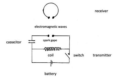
|
Conceptual Schematic of Hertz's Experiment |
In this experiment Hertz confirmed Maxwell’s theories about the existence of
electromagnetic radiation.
In more advanced experiments, Hertz measured the velocity of electromagnetic
radiation and found it to be the same as the light’s velocity. He also
showed that the nature of radio waves’ reflection and refraction was the
same as those of light, and established beyond any doubt that light is a
form of electromagnetic radiation obeying the Maxwell equations.
Summing up Hertz's importance: his experiments would soon trigger the
invention of the wireless telegraph and radio by Marconi and others and TV.
In recognition of his work, the unit of frequency - one cycle per second -
is named the “hertz”, in honor of Heinrich Hertz.
Repeat Hertz’s Experiments
Warning: experiments with electricity should
be performed under the supervision of teachers or adults familiar with
electricity safety procedures. Especially, take in account that experiments
with induction coils and capacitors can produce high voltage shocks.
Hertz first experiment – creating, sending and detecting radio waves – is
relatively simple, not beyond the abilities of middle school students. In
order to begin, read carefully the experiment links and ensure that you
understand the basic principals. Brows further the web and consult your
local library, your teacher and other knowledgeable adults and experts.
Hertz’s more advanced experiments, mentioned above, require some extra
ability and knowledge, and in order to perform these experiments
successfully the students are also required to be able to read and
understand a few books by Hertz or about Hertz listed in the resource
section.

Hertz’s Experiment
- Perform an investigation to demonstrate the production and reception of radio waves
Hertz demonstrated the production of radio waves and confirmed Maxwell’s prediction that there were EM waves with frequencies outside the visible light spectrum.
Aim
Hertz wanted to produce EM waves with frequencies and wavelengths other than visible light.
Setup and Method
An induction coil was used to create a rapidly oscillating B-field which caused a rapid sparking across a gap between spherical electrodes in a conducting circuit.
This circuit formed the transmitter and a receiving loop also with a gap in it, was placed some distance from the transmitter.
The high voltage induction coil connected to the transmitter was switched on and changes observed
Changes in the receiving electrodes were observed

Observations and Explanations
When the power was on, sparking occurred between the electrodes at the transmitter and this also resulted in sparks at the receiver.
- The high voltage AC produced sparking and a rapidly oscillating electric field which gave rise to a magnetic field and so on.
- Thus, EM radiation (radio waves) were produced and traversed the distance to the receiver
- The EM radiation travelling towards the receiver struck the electrodes of the receiver, energising electrons in the conducting surface and caused them to jump across the gap as a spark.
- Note: there were no electrical connections between the transmitter and receiver
Other properties observed
- Reflection – Hertz reflected waves off a zinc plate and they still reached receiver to cause sparking
- Refraction – Radio waves were refracted through a prism
- Polarisation – He rotated the receiver’s plane
relative to the transmitter
- The receiver’s intensity and length of sparking at the receiver was a maximum when the plane was parallel and a minimum when perpendicular.
- Interference – he observed that waves reaching the receiver from 2 different paths interfered constructively and destructively to produce interference pattern of light and dark patches.
- Distance – the length and intensity of sparking at the receiver was not affected by the distance between transmitter and receiver. Suggested that light waves are self-propagating
- Speed – The speed was accurately measured to be “c” (see next dot point)
Conclusions
These observations strongly supported Maxwell’s prediction of EM radiation and model of light: self-propagating, transverse waves of alternating electric and magnetic fields that are perpendicular to one another. Hertz concluded that radio waves were able to cause sparking at the receiver.
Photoelectric Effect observation
- Describe Hertz’s observation of the effect of a radio wave on a receiver and the photoelectric effect he produced by failed to investigate
The photo electric effect is the emission of electrons from the surface of a conductor when it is subject to EMR.
- This was first observed by Hertz in 1887 but he did not create the above definition.
- He enclosed the receiver in a dark box to create a dark environment for making observations.
- In doing so, he observed that the length and intensity of sparking diminished.
- On removing the various walls of the box in succession, he found that only the portion of the case which shielded the receiver from the transmitter had this effect on sparking.
- Hertz knew that radio waves produced by the transmitter would not be blocked by the box so he reasoned that the box must be blocking other type of EM waves.
This led onto further investigations and observations.
- The length and intensity of sparking at the receiver was diminished when glass (blocks UV) was used as a shield between transmitter and receiver.
- Then quartz was used (quartz does not block UV) and no change to the sparking was observed
- When a mercury vapour lamp (emits UV) was shone onto the receiver, sparking was increased.
He named these effects the photo electric effect but did not investigate any further.
Hertz’s experiment to measure the speed of radio waves
- Outline qualitatively Hertz’s experiments in measuring the speed of radio waves and how they relate to light waves
In order to prove that these radio waves were EM waves, he showed they had similar properties to light, namely its speed.
Measuring the Speed of Radiowaves
- In order to determine velocity
 ,
Hertz needed to measure frequency and wavelength.
,
Hertz needed to measure frequency and wavelength. - The frequency of the waves was already known, as Hertz had used an RLC (resistor inductor capacitor) in his set up. This produced a sinusoidal current of constant frequency.
- To measure the wavelength, radio waves were allowed to reach the receiver from 2 different paths – one directly and one following reflection off a metallic surface.
- These two waves met at the receiver and created an interference pattern of light and dark patches corresponding to relative max and min.
- By moving the receiver back and forth, the interference pattern of the waves could be analysed
- The difference between successive maxima or successive minima gave

Conclusion: Hertz then found the speed of radio waves
using and
found 

Microwave Energy - the next part of my Making Electromagnetic Weapons series. For the Electromagnetic Pulse Generator, check out the last three articles
I'm sure almost all of you have used a microwave at some point in your lives. As a child, I always found microwaves fascinating; the idea of heating food with invisible energy, and even creating lightning should the user accidentally microwave metal! However, microwaves are not only used for heating food. Microwave energy generally falls under the 2.4 GHz (Gigahertz band). This same band is used by many wireless technologies such as Bluetooth and Wi-Fi. Microwaves consist of any wavelength between 300 MHz (0.3 GHz) and 300 GHz. The range (energy) depends on the "strength" of the wavelength.
Here's a visual representation of the electromagnetic spectrum:

Simple Cooking Appliance or Lethal Weapon?
Well, it really depends. In this article, I'll be going over the simple basics of a microwave weapon, since microwave energy is a huge topic. In its simplest form, any waveform transfer of energy starts with excited particles and ends with excited particles.
Inside a microwave, you'll find a large transformer (called a MOT or Microwave Oven Transformer), a large capacitor (rated around 1-2 kV; 1-100 uF), some high voltage diodes (for rectifying the alternating current from the transformer), a magnetron (the microwave emitter—I'll go into this later), and other electrical components for operating the main electronics.
In a Microwave Weapon (MW), the components can be as simple as a magnetron, a transformer, a diode, and a capacitor. Of course, the magnetron is certainly not that simple, consisting of several finely tuned "antennas" and other components. A basic illustration of how a magnetron works is pictured below:

The round "1" is an electron source, the area between the power source and the antenna is the electron "accelerator", and the antenna itself is a simple way of "amplifying" and broadcasting the electron energy at a specific frequency. When these "tuned electrons" hit an object (specifically water or metal), they excite the molecules and generate heat, or in the case of metal, electrical energy. This is why microwaves are so dangerous compared to EMPs. Microwaves not only wreck havoc on electronics, but also can harm living beings.
This is where I must issue a WARNING!!! Microwaves are extremely dangerous. They can PERMANENTLY HARM YOU! If you feel even the slightest uncertainty towards the physics, dangers, and overall understanding of microwaves, DO NOT construct a microwave weapon.
The Construction
The best way to create a homemade microwave weapon is with an old microwave. If you want to upgrade to a more powerful, long range device, it's practically impossible unless you have a physics lab with extensive measuring equipment. However, an average microwave puts out 1,000-2,000 watts of energy, quite enough for destroying electronics.
Microwaves tend to "fly in all directions" unless they are directed. However, this is what the antenna does—directs the microwaves. In my experimentation, I discovered that a slight cone-shaped metal funnel has the best microwave-focusing ability. I was able to fry an old cell phone from up to 10 feet using three magnetrons and one funnel. This constitutes to about 6,000 watts (W) of directed energy, quite an accomplishment for 15 bucks spent at a thrift store. The circuit diagram for each individual magnetron looked something like this:

On a basic level, the circuit consists of a transformer, a voltage doubler (diode and capacitor) and a magnetron. The three MOTs draw lots of power, so I had to hook everything into a thick, direct mains line. The magnetron itself looks like this:

There are two large magnets that "direct" the electrons as they pass through the antenna. Also, the device has a heat sink to cool off. There are many other components and function aspects of the magnetron that are very complicated, but interesting. If you're curious, check out the information in this article.
Once finished, the entire apparatus should look something like this:

The waveguide (or metal funnel cone) guides the microwaves in a linear direction, and allows them to be focused in a specific direction. Once directed, the microwaves can generate electrical current in any conductive metal they encounter. How much electricity they generate is determined by the distance from the magnetron and the power of the output. The microwave gun will also disrupt wireless communications (depending on their frequencies) and excite water molecules.
Warnings
- MICROWAVES ARE VERY VERY DANGEROUS. DO NOT attempt to build this device unless you are very very confident in your understanding of the dangers, correct practice of safety, and legal concerns.
- HIGH VOLTAGE! Microwave Transformers can easily kill you! Treat then with respect! Remember... Fear of Lightning.
- DO NOT use this device on anything or anywhere where it violates FCC rules or any other legal constraint!
- I am not responsible for any damage, harm, or legal trouble you get yourself into.
Antenna (radio)
An antenna (plural
antennae or antennas), or aerial, is an electrical device which converts
electric power into radio waves, and vice versa. It is usually used with a
radio transmitter or radio receiver. In transmission, a radio transmitter
supplies an electric current oscillating at radio frequency (i.e. a high
frequency alternating current (AC)) to the antenna's terminals, and the
antenna radiates the energy from the current as electromagnetic waves (radio
waves). In reception, an antenna intercepts some of the power of an
electromagnetic wave in order to produce a tiny voltage at its terminals,
that is applied to a receiver to be amplified.
Antennas are essential components of all equipment that uses radio. They are
used in systems such as radio broadcasting, broadcast television, two-way
radio, communications receivers, radar, cell phones, and satellite
communications, as well as other devices such as garage door openers,
wireless microphones, Bluetooth-enabled devices, wireless computer networks,
baby monitors, and RFID tags on merchandise.
Typically an antenna consists of an arrangement of metallic conductors
(elements), electrically connected (often through a transmission line) to
the receiver or transmitter. An oscillating current of electrons forced
through the antenna by a transmitter will create an oscillating magnetic
field around the antenna elements, while the charge of the electrons also
creates an oscillating electric field along the elements. These time-varying
fields radiate away from the antenna into space as a moving transverse
electromagnetic field wave. Conversely, during reception, the oscillating
electric and magnetic fields of an incoming radio wave exert force on the
electrons in the antenna elements, causing them to move back and forth,
creating oscillating currents in the antenna.
Antennas can be designed to transmit and receive radio waves in all
horizontal directions equally (omnidirectional antennas), or preferentially
in a particular direction (directional or high gain antennas). In the latter
case, an antenna may also include additional elements or surfaces with no
electrical connection to the transmitter or receiver, such as parasitic
elements, parabolic reflectors or horns, which serve to direct the radio
waves into a beam or other desired radiation pattern.
The first antennas were built in 1888 by German physicist Heinrich Hertz in
his pioneering experiments to prove the existence of electromagnetic waves
predicted by the theory of James Clerk Maxwell. Hertz placed dipole antennas
at the focal point of parabolic reflectors for both transmitting and
receiving. He published his work in Annalen der Physik und Chemie (vol. 36,
1889).

Animation of a half-wave dipole antenna transmitting radio waves, showing the electric field lines. The antenna in the center is two vertical metal rods, with an alternating current applied at its center from a radio transmitter (not shown). The voltage charges the two sides of the antenna alternately positive (+) and negative (−). Loops of electric field (black lines) leave the antenna and travel away at the speed of light; these are the radio waves.

Animated diagram of a half-wave dipole antenna receiving energy from a radio wave. The antenna consists of two metal rods connected to a receiver R. The electric field (E, green arrows) of the incoming wave pushes the electrons in the rods back and forth, charging the ends alternately positive (+) and negative (−). Since the length of the antenna is one half the wavelength of the wave, the oscillating field induces standing waves of voltage (V, represented by red band) and current in the rods. The oscillating currents (black arrows) flow down the transmission line and through the receiver (represented by the resistance R).

Standing waves on a half wave dipole driven at its resonant frequency. The waves are shown graphically by bars of color (red for voltage, V and blue for current, I) whose width is proportional to the amplitude of the quantity at that point on the antenna.

Diagram of the electric fields (blue) and magnetic fields (red) radiated by a dipole antenna (black rods) during transmission.
1- Quarter-wave whip antenna on an FM radio for 88-108 MHz
2- Rubber Ducky antenna on UHF 446 MHz walkie talkie with rubber cover
removed.

3- Rabbit ears half-wave dipole television antenna for VHF channels 54-217
MHz

4- Yagi-Uda television antenna for analog channels 2-4, 47-68 MHz
5- Log-periodic antenna covering 140-470 MHz

6- Two-element turnstile antenna for reception of weather satellite data,
137 MHz. Has circular polarization.
7- 108 MHz reflective array antenna of AN-270 radar used during WW2.

8- Reflective array UHF TV antenna, with bowtie dipoles to cover the UHF
470-890 MHz band

9- Ferrite rod receiving antenna from AM radio, 550 - 1600 KHz. The antenna
also serves as the inductor in the tuned circuit for the receiver.

- Quadrant antenna, similar to rhombic, at an Austrian shortwave broadcast station. Radiates horizontal beam at 5-9 MHz, 100 kW

10- Loop direction finding antenna covers 1.75 - 30 MHz, 6 ft diameter

11-NASA Cassegrain parabolic spacecraft communication antenna, Australia.
Uses X band, 8 – 12 GHz. Extremely high gain ~70 dBi.

12- Microwave horn antenna bandwidth 0.8–18 GHz

13- X band marine radar slot antenna on ship, 8 – 12 GHz.

We know that electric current produces a magnetic field. We also know that when a conducting loop is moved through a magnetic field, we have electric current induced in the loop. Thus time varying electric and magnetic fields produce each other. This symmetry is very interesting and is one of the most fundamental observations in physics.
James Clark Maxwell (1831 – 1879) formulated a set of equations to explain these effects. There are four equations known as Maxwell′s equations that deal with electric and magnetic fields and their sources (charge and current densities). Together with the Lorentz force equation, the Maxwell′s equations give mathematically all the basic laws of electromagnetism.
The most important outcome of Maxwell′s equation is the presence of electromagnetic wave. Electromagnetic wave propagates in medium when there is a time varying electric and magnetic field present and the speed of propagation is close to the speed of light.
Far reaching conclusion was drawn from this observation – that light itself is an electromagnetic wave. At the heart of production of electromagnetic waves is an oscillating electric charge. These oscillating charges produce an oscillating magnetic field (or flux) and an oscillating magnetic field, in turn, produces an oscillating electric field!

Charge density (ρ)
Charge density is a measure of electric charge per unit volume of space,
in one, two or three dimensions. The linear, surface, or volume charge
density is the amount of electric charge per unit length, surface area,
or volume.
Current density (J)
Current density is a measure of the density of flow of a conserved
charge, in other words flux of the charge.
Electric displacement field (D)
In a dielectric material the presence of an electric field E
causes the bound charges in the material to slightly separate,
inducing a local electric dipole moment. The electric displacement field
D is defined as
D = ε0 E + P
where ε0 is the permittivity of free space, and P
is the (macroscopic) density of the permanent and induced electric
dipole moments in the material, called the polarization density.
Separating the total volume charge density into free and bound charges.
[
Ana Sayfa (Home)
|
UFO Technology
|
UFO's
Galleri | Kuantum
Fiziği | Roket bilimi
|
[ Astronomy |
E-Mail
| Index
|