General Mission Summary and Configuration Description
Posted by Randy Attwood - Source: NASA
Posted April 18, 1966 9:23 AM
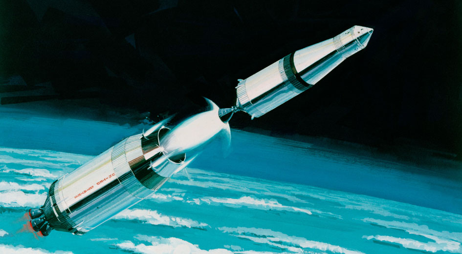
Separation of second and third stages
General Mission Summary and Configuration Description
By Owen E. Maynard and John R. Sevier
This section of the Symposium will describe the first Apollo lunar
landing mission in its entirety - from lift off to recovery. It is
intended to provide the general framework for a proper understanding of
the subsequent presentations which will explore particular aspects of the
mission in considerably greater detail.
PLATEAUS AND GROSS MISSION DESCRIPTION

Figure 01
It is useful to think of the lunar landing mission as being planned in a series of steps (or decision points) separated by mission "plateaus" (Figure l). The decision to continue to the next plateau is made only after an assessment of the spacecraft's present status and its ability to function properly on the next plateau. If, after such as assessment, it is determined that the spacecraft will not be able to function properly, then the decision may be made to proceed with an alternate mission. Alternate missions, therefore, will be planned essentially for each plateau. Similarly, on certain of the plateaus, including lunar stay, the decision may be made to delay proceeding in the mission for a period of time. In this respect, the mission is open-ended and considerable flexibility exists. This flexibility will be discussed in detail throughout the symposium.
It will be convenient, for purposes of overall mission description, to quickly go through the mission plateaus and decision points. Following this gross description, the operations for each plateau will be examined in greater detail.
The end points of these plateaus representing major "commit" points in the lunar landing mission are characterized by propulsive maneuvers resulting in major changes in the spacecraft energy. These commit points and mission plateaus can both be represented schematically on a single chart as shown in Figure 2.

Figure 02
Figure 2 illustrates the major maneuvers during the lunar landing mission
in terms of both delta V (on the left) and pounds of propellant (on the
right). These maneuvers repre¬sent the "commit" points, and the space in
between represents the plateaus. A pictorial representation of the mission
is illustrated in Figure 3, in which the Earth, the Moon, and their
relative movement throughout the mission are shown to scale in an earth
centered coordinate system. The spacecraft's orbits about the earth and
moon are, of course, not to scale.
The first plateau, pre-launch, terminates at launch from the Complex 39 facility at Merritt Island. The launch to earth orbit is performed with the first two stages and a partial burn of the third stage of the Saturn V launch vehicle. As shown in Figure 2, the earth ascent phase represents the major expenditure of propellant for the lunar landing mission, approximately 5½ million pounds of propellant has been expended to place the approximately 300,000 pound payload in earth orbit.

Figure 03
Referring to Figure 3, the earth ascent phase is shown schematically as it might be seen from some distant point in space looking down on the earth-moon plane. The moon's position at launch is shown in the lower right hand corner, and its daily movement, as the mission continues, is shown at successive points.
Following the ascent, the spacecraft reaches the second mission plateau, earth parking orbit. During each parking orbit, which can last up to 4½ hours, spacecraft systems are checked out and made ready for the next major maneuver, translunar injection. As shown in Figure 2, translunar injection represents a consider¬able change in spacecraft energy; the velocity is increased by some 10,000 ft/sec with a propellant expenditure of about 150,000 lbs. from the second burn of the launch vehicle's third stage.
Following translunar injection, the spacecraft is on the next plateau, translunar coast. An initial period of ground tracking is performed to confirm that the spacecraft is on a satisfactory trajectory, and following this confirmation, the transposition and docking operation is performed. This operation involves the Command and Service Modules (CSM) separating from the rest of the configuration, turning around and docking on the Lunar Module (LM), which is still attached to the S-IVB, and continuing the translunar coast. Sufficient separation velocity is applied by the Service Module Reaction Control System (RCS) to assure that there is no possibility of subsequent recontact with the S-IVB.
The spacecraft continues to coast on the translunar leg of the trip for approximately the next three days. Two or three mid-course corrections will be made by the Service Propulsion System (SPS) during the translunar coast phase to assure that the spacecraft arrives at the correct location for its next major burn, lunar orbit insertion.
The lunar orbit insertion maneuver occurs behind the moon after the spacecraft has passed out of line of sight to earth. The maneuver is performed with the SPS and requires approximately 3500 ft/sec delta V and 25,000 lbs. of propellant. If the lunar orbit insertion maneuver is not performed for some reason, then the spacecraft merely circumnavigates the moon and returns to safe earth entry conditions on the free return trajectory with no SPS engine burns required.
The successful execution of the lunar orbit insertion maneuver, however, will have placed the spacecraft in a circular orbit about the moon at an 80 nautical mile altitude. This is the next plateau. After at least three revolutions in lunar orbit, the LM is separated from the CSM and the two man crew begins their descent to the lunar surface, leaving a single crewman behind in the Command Module (CM).
The initial deboost of the LM from its 80 nautical mile orbit is made behind the moon and is performed by a small impulse from the LM descent engine. Following a coast period of about one hour, during which the LM has slowly descended to 50,000 ft. altitude, the descent engine is again ignited and the main braking maneuver is initiated. From this point, the descent to the surface requires about 10 minutes, the latter portion of which is under manual control of the crew. As noted in Figure 2, the fuel expenditure for this maneuver has been over 15,000 lbs., with an equivalent delta V of about 6500 ft/sec.
Following the lunar landing, the crew will secure the LM, don their extravehicular life support equipment, and exit to the lunar surface. During the 18 hour lunar stay period, there will be two exploration periods of three hours each performed by both crewmen. The extravehicular activity will consist of sample collection, emplacement of the experiments package for long term operation, photography and general geological observation. Following the return from the last exploration period, the crew performs the pre-launch checkout of the LM systems and prepares for launch. At the proper time, with the CSM approximately 10 degrees ahead of LM, the ascent engine is ignited, and the LM ascent stage lifts off from the moon, leaving the descent stage on the surface. Although the ascent trajectory involves several maneuvers from lift-off until rendezvous with the CSM is accomplished, the most significant of these is the main powered ascent which involves a continuous engine burn from the surface to burnout at 50,000 ft. altitude. From Figure 2, it may be seen that about 5000 lbs. of propellant is expended with an equivalent delta V of about 6000 ft/sec. The conclusion of the main ascent burn at 50,000 ft. is such that the LM is placed on a safe coasting trajectory which will not impact the moon, even if the subsequent rendezvous maneuvers were not made for some reason. This leaves the LM in a relatively stable situation from which rescue by the CSM could be made, if necessary. However, the planned ascent phase continues with a series of small impulses provided by the LM RCS, and rendezvous occurs with the CSM about two hours after lift-off.
After the LM has docked on the CSM, the LM crew is transferred to the CSM, along with the data and samples collected on the lunar surface. The LM is then jettisoned, and preparations are made for the next major maneuver, transearth injection. The delta V required is slightly less than for lunar orbit insertion, and the propellant expendi¬ture for the SPS is considerably less, about 8000 lbs. since the spacecraft is considerably lighter.
It is of interest to note that up until the LM began its descent operations, a backup for transearth injection was available in the LM descent engine. This is considered a particularly useful capability, since it allows one to guard against an SPS failure during its first major burn for lunar orbit insertion. For this reason, then, the propellant requirement for transearth injection is also shown in terms of what would be required from the LM descent propulsion system, approximately l4,000 lbs.
Following the transearth injection, the spacecraft is on a plateau much like the outgoing leg of the trajectory to the moon. It is targeted to arrive at safe entry conditions at the proper time to allow it to reach its primary recovery area in the Pacific Ocean. Small midcourse corrections during the transearth coast assure that these conditions are reached. Shortly before arrival at the entry point, the Service Module is jettisoned, and the CM is oriented for entry. Entry range varies between 1500 and 2500 nautical miles and is controlled by rolling the CM during the entry phase. At 25,000 ft. altitude, the drogue parachutes are deployed and followed a short time later by the main parachutes which slow the CM to safe touchdown conditions.
Recovery is soon effected, and with the CM and crew safe aboard ship, the mission is completed.
Having completed this gross description of the total mission, it will be of interest to devote some attention to a few basic mission planning considerations before proceeding with the more detailed description of the mission.
PLANNING FOR LAUNCH ATTEMPTS, LUNAR LIGHTING AND SITE SELECTION
This section will consider launch attempts at the earth, the lighting conditions for landing at the moon, and any intervening accumulators that could contribute to a balanced planning scheme for a first manned landing attempt. Consider first the question of launch attempts at the earth: very briefly, it is highly advantageous to allow at least 48 hours between each of 2 or 3 scrubs. Certainly more than one 2 1/2 hour launch window per month is required because of the reasonably high probability of scrub against a particular scheduled time, and the resulting impact on the following program is high.
The causes of scrubs and holds could be due to launch vehicle, spacecraft, launch complex or MSFN systems problems, or possibly weather.
Probability of scrub has historically, and for good reason, increased markedly after the time it becomes necessary to recycle in the event of a scrub.
Recycle time is controlled by "fix" time, holding limits, servicing cycle, weather, launch and control team recycle and flight crew change time. It is interesting to note here that although there are multiple shifts involved there are no complete backup teams except in the case of the flight crew. Historically, and again for good reason, recycle times are most frequently in excess of 24 hours and usually more like 48 hours.
The probability of a scrub against a particular scheduled launch time is reasonably high: approximately 1/3. The probability of launch, therefore, increases markedly as multiple recycles are allowed: starting at about .67 for no recycle, .89 for one recycle, .96 for two recycles, and .99 for three recycles. Since the recycle time is usually in the neighborhood of 48 hours, then planning launch opportunities for consecutive days will not significantly increase the probability of launch over that which considers only alternate days as opportunities. From these considerations, then, it is highly advantageous to provide some accumulator time in the system to permit at least two and possibly three recycles of at least 48 hours each (Figure 4).
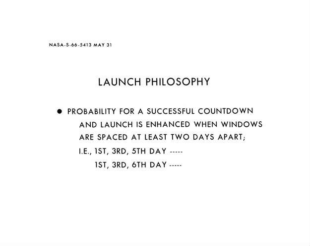
Figure 04
Before considering the implications of this, another basic constraint will be examined; namely, the lighting requirements at the moon. Present understanding of the nature of the photo¬metric function at the moon, and more direct observation as well, leads to the conclusion that there probably exists a small range of sun elevation angles where a flight crew's ability to select an acceptable touchdown point is markedly improved over angles outside that range. Again, present understanding of the nature of the lunar surface leads to the conclusion that it is necessary to provide a high capability in this area in order to enhance mission success and crew safety. The first lunar landing mission is now being planned for sun elevations between 7° and 20° to take maximum advantage of the crew's visibility in the landing operation (Figure 5).

Figure 05
Since there is only a range of 13° in the planned sun elevation angle, and since sun elevation angle changes at the rate of 26° for a single 48 hour recycle, 52° for two recycles, and 780 for three recycles, then this obviously leads one to look at multiple landing sites.
Some slight flexibility in launch to a single site could be realized if accumulators were used as built-in holds. That is, plan to launch early after a successful countdown, and wait at some point in the mission for the planned landing site to catch up to the correct lighting condition. For example, additional earth orbits and lunar orbits could be used as built-in holds at the rate of 1/2° per hour (3/4° per earth orbit and 1° per lunar orbit). Similarly, trans¬lunar transit time could be used as an accumulator at this same rate. Since there is a limitation of only three earth orbits (from S-IVB consumables considerations), and since the free return trajectory requirement restricts translunar transit time to a narrow range, then about the only significant flexibility item is in the number of lunar orbits prior to LM descent. However, to make full use of this, one would sometimes launch so early that more than 70 hours in lunar orbit would be required to rectify the lighting conditions at the landing site. Consumables and systems limitations would then become a problem.
Therefore, the multiple landing site philosophy becomes an inherent
feature in lunar mission planning.
Apollo mission planning personnel have, of course, been involved in Lunar
Orbiter and Surveyor site selection. The sites shown on Figure 6 are from
the Orbiter A and Orbiter B missions as planned to be flown later this
year. These particular sites have been identified at this point in time as
most probable to contain acceptable touchdown points in a large dispersion
ellipse and radar approach terrain.

Figure 06
Considering now the question of spacecraft performance, Figure 7 shows the dates in 1968 when certain of these sites can be achieved with the 7° to 20° sun elevation. In generating the performance scan, a 95,000-pound spacecraft was assumed loaded with 37,500 pounds of SPS propellant of which 1% was retained for reserve.

Figure 07
It is apparent that changing the magnitude of sun elevation would shift the days that a particular site could be reached. Increasing the range of sun elevation would increase opportunities and decreasing the range of sun elevation would obviously decrease opportunities.
Figure 7 (for Pacific injections) and Figure 8 (for Atlantic injections) show that availability of a considerable number of potential sites generally clustered in three groups which are separated in longitude such that a 48 hour recycle back at earth launch could be accommodated as planning is shifted westerly from one group to the next.

Figure 08
It is apparent from Figures 7 and 8 that Pacific injections (with daylight launches) are available during most of the year. During the latter part of the year, Atlantic injections would probably be used, and night launches would be necessary.
The distributions for 1967 and 1969 are not markedly different from 1968. Figures 9 and 10 illustrate the landing site accessibility for 1969.

Figüre 09

Figure10
Figures 11 and 12 illustrate this mission planning concept for typical launch dates in 1968 and 1969 to three of the candidate sites. These figures show how the earth, moon, and sun cooperate to give a reasonable mission concept allowing two 48-hour recycle times at the launch pad and near optimum lighting at the moon. The precise targeting points would not have to be determined until about 6 months before the mission.

Figure 11

Figure 12
Data for site selection starts with earth-based photography, radar, IR, and other observations, which, at this point in time, have lead to the selection of a relatively large number of contender sites for Apollo landing. This number will decrease as Orbiter and Surveyor data lead to conclusions as to which are the better sites in the three groups. By 6 months before the mission it would be highly desirable to have narrowed these sites down to one in the east, one in the central portion, and one in the west.
The scientific objectives of at least the early mission have been developed so that they may be achieved virtually independent of the site location.
Having established these basic mission considerations of launch opportunities, lunar lighting, and site selection, we will now return to the mission itself and examine it in more detail.
DETAILED MISSION DESCRIPTION

Figure 13
Figure 13 illustrates the orientation of the space vehicle on the launch pad. The spacecraft's -Z axis (direction of crew's heads), and the launch vehicle's Position I are pointing east. In the event of a pad abort at this point, the orientation is such that the trajectory of the launch escape vehicle would take the Command Module over the water.
The inner gimbal of both the spacecraft's and launch vehicle's Inertial Measurement Unit (IMU) are aligned normal to the upcoming orbit plane.
EARTH ASCENT
Lift off occurs after a 6-second hold down period following engine ignition (Figures 14 and 15). During this time, the thrust of the first stage, which is powered by five F-1 engines, has built up to its rated value of 72 million pounds. The thrust-to-weight ratio of the vehicle at this point is 1.25, so its initial ascent acceleration is relatively small.
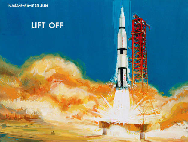
Figure 14
The space vehicle rises vertically from the launch pad until the mobile launcher is cleared. It then performs a roll maneuver to align the launch vehicle Position I along the desired launch azimuth, which can vary between 72° and 108°. The orientation on the pad was such that Position I was pointing east.
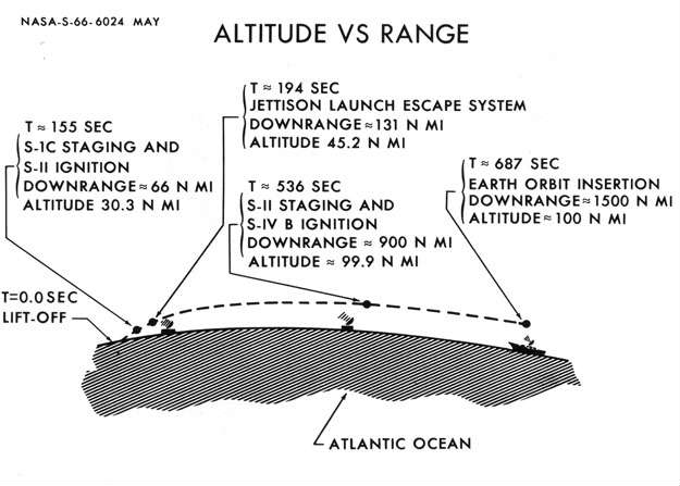
Figure 15
Following the vertical rise period, which lasts 12 seconds, a programmed pitch is commanded which will continue throughout the first stage burn. Maximum dynamic pressure (700 psf) is reached at about 84 seconds at an altitude of 43,000 feet. The inboard engine cutoff of the first stage will occur about 155 seconds after liftoff and will be followed by the outboard engines cutoff four seconds later. During this first stage operation, the spacecraft will have attained an altitude of about 200,000 feet and will be about 65 nautical miles down range. Maximum acceleration will have occurred at this point and amounts to about 4 1/2 g's. Tracking and communications will have been continuous during this period with the ground-based facilities in the Cape area and with the facilities at Grand Bahama during the latter portion of the burn.
Since the launch vehicle operations during this period are automatic, the crew has been functioning in mainly a capacity of monitoring launch events and communicating the occurrence of these events to the ground. Critical spacecraft systems are being checked and abort readiness maintained. An Emergency Detection System is provided onboard for sensing various malfunctions of the launch vehicle and displaying this information to the crew, who can then initiate an abort, if necessary. Automatic abort capability is maintained to nearly the end of first stage operations to allow for extremely time critical situations.
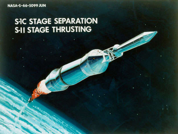
Figure 16
Following cutoff of the outboard engines of the first stage, thrust decay to 10% occurs in about one-half second, at which time the second stage ullage rockets and first stage retro-rockets are fired, and S-IC/S-II separation occurs (Figure 16).
The S-II stage is powered by five J-2 engines, each having 200,000 pounds of thrust. Thrust buildup to the rated value occurs rapidly and at 163 seconds after liftoff, the second stage has reached full thrust.
At this point, the switchover is made from the programmed-pitch guidance scheme, used during first stage operations, to a path-adaptive scheme used during second and third stage operations. All guidance equipment for the launch vehicle is contained in the Instrument Unit located between the S-IVB stage and the spacecraft adapter. As stated previously, all guidance opera¬tions during ascent are performed automatically by the launch vehicle. However, from this point on in the ascent, the capability exists onboard the spacecraft to take over the guidance function in the event of a failure of the launch vehicle inertial platform.
Approximately 2 5 seconds after S-II ignition, the S-IC/S-II forward interstage is jettisoned, and this is followed by the Launch Escape System jettison five seconds later (Figure 17). Up until this point, the Launch Escape System has been the means of safely removing the CM and crew away from a malfunctioning vehicle in the event an abort was necessary. The high thrust and acceleration capability of the Launch Escape System motors was required to accomplish a safe abort during the atmospheric portion of the flight. At this point in the mission, however, the Service Propulsion System has the capability to abort the spacecraft off the launch vehicle, so the LES is jettisoned.
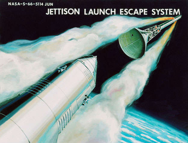
Figure 17
The Boost Protective Cover is attached to the LES and is jettisoned at the same time. The BPC is a semi-soft fiber¬glass construction, and its function has been to absorb the CM aerodynamic heating during boost and to provide a protective shield to maintain a satisfactory thermal control surface during the rest of the mission back to entry. The actual jettison operation of the LES, however, produces another thermal problem. The exhaust products of the solid jettison motors will impinge on the clean surfaces of the CM and SM and degrade the thermal performance to some extent. The complete nature of this problem is currently being investigated in ground tests and will be investigated in the early development flights. A later paper in the Symposium will discuss this in detail.
The second stage burn continues for a total duration of about 375
seconds, a little more than 6 minutes. At this point, orbital altitude of
100 nautical miles has essentially been reached but the spacecraft is
still short of orbital velocity by about 3000 ft/sec. (Inertial velocity
is about 22,650 ft/sec.) The vehicle is almost 900 nautical miles down
range from Cape Kennedy. The tracking stations at the Cape are out of
range by this time but other stations at Grand Turk or Bermuda have picked
up the space vehicle, so that communications have been uninterrupted.
Figure 18
Following shutdown of the five J-2 engines on the S-II stage, S-Il/S-IVB separation occurs, and third stage operations begin (Figure 18). The separation sequence is similar to the one described for S-IC/S-II stage separation -- the S-II retro-rockets and S-IVB ullage rockets fire and pyrotechnic devices separate the stage. The problem mentioned previously of thermal coating degradation from the LES jettison motors is similar to one which occurs during S-Il/S-IVB separation in that the S-II retro-rocket gases impinge on the Service Module thereby degrading its thermal coating. As mentioned previously, this problem is currently under investigation.
The S-IVB burn during the boost phase lasts for about 2.5 minutes and imparts some 3000 ft/sec to the spacecraft velocity--boosting it up to the orbital velocity of about 25,600 ft/sec. Thrust of the S-IVB stage is about 200,000 pounds produced by the single J-2 engine. At the conclusion of the S-IVB burn, the spacecraft is at 100 nautical miles altitude and has traveled another 600 nautical miles downrange for a total distance during the boost phase of almost 1500 nautical miles. The total ascent has taken about 11.5 minutes (Figure 19).

Figure 19
During this third stage burn, communication with the land-based stations has been lost, but the spacecraft has been acquired by the insertion ship which has been specifically located to fill in this gap and to provide a period of tracking immediately after insertion for the purposes of confirming a safe orbit, and issuing the decision to continue the mission. The insertion ship coverage is shown in Figure 20.

Figure 20
EARTH PARKING ORBIT

Figure 21
Following this confirmation of a good orbit, the spacecraft is on the second mission plateau which was discussed earlier (Figure 21). The capability exists to spend up to three complete revolutions in the earth parking orbit, but normally the plan will be to execute the next commit point, translunar injection, during the second revolution. The limitation of three revolutions is associated with considerations of S-IVB consumables limitations. A later paper in the Symposium by M. P. Frank will discuss the geometry of trans¬lunar injection opportunities will occur every day over both the Atlantic area and the Pacific area, but one of these will be preferred from a performance standpoint. In addition, it is not planned to have support aircraft covering both areas simultaneously. There¬fore, having planned the mission for a specific period during a specific month, and have launched at a specific time of day, then the mission is committed to either a Pacific or Atlantic injection. For reference purposes, the Pacific injection will be considered as the appropriate window, and for the reference mission, it will occur over the Western Pacific Ocean, near the equator. The only parameter left to choose is which of the three opportunities during the three revolutions translunar injection will occur. The answer to this question is dependent upon how extensive a set of operations is planned during earth parking orbit. These operations will be discussed below. Figure 22 shows the ground track and station coverage for the typical reference missions; it will be useful to refer to this figure during the discussion of earth orbit operations.

Figure 22
Immediately after S-IVB cutoff at earth orbit insertion, the launch vehicle propellant tanks are vented of hydrogen and oxygen gases to relieve the pressure buildup. Venting is performed at this time in order to prevent unpredictable vents from interfering with sensitive attitude operations later on. The venting sequence is preceded by ullage rocket firing to assure propellant settling sc that only vapors are vented. After settling the propellant, the oxygen tanks are vented for about 15 seconds. Hydrogen venting will be done continuously throughout earth orbit, along the spacecraft's thrust axis; however, the propulsive force of the hydrogen venting is extremely low and, therefore, would not interfere with other operations during earth orbit.
Following earth orbit insertion the crew remains in their couches until the Manned Spaceflight Network (MSFN) has verified that the spacecraft is in a safe orbit. This confirmation is provided after about three minutes of tracking by the insertion ship in the Atlantic. At this time a sate vector update is provided by the ground which the crew inserts into the onboard computer.
Following a brief onboard checkout of spacecraft systems, the navigator will leave the center couch and go the lower equipment bay of the Command Module and prepare for the first operation--the alignment of the CM inertial Platform. This is done both as checkout of the IMU and its associated equipment and to establish a precise onboard inertial reference as a backup to the inertial reference in the S-IVB Instrument Unit.
The spacecraft attitude at this point is such that the longitudinal axis is in the local horizontal and pointed in the direction of flight. This local horizontal mode is maintained automatically throughout the earth orbit phase by a constant pitch rate equal to the orbital rate of .067 deg/sec. The S-IVB control system provides this mode and maintains it within a one-degree deadband. This orientation in the local horizontal mode assures communication coverage of the spacecraft and launch vehicle antennas when passing over a ground station.
The crew takes over manual control of the vehicle attitude through the S-IVB control system during spacecraft operations requiring specific attitudes. This is the case during the IMU alignment mentioned earlier. Depending on the time of day that launch occurred, the sun location may interfere with the optics line of sight during the IMU alignment. A roll maneuver would then need to be performed by the CM crewman before beginning the alignment. Following the alignment, the crew would return the vehicle to the original roll orientation with the -Z axis of the spacecraft pointing down the local vertical.
Because of the relatively high inertias of the vehicle, these maneuvers must be performed at relatively slow rates to conserve S-IVB RCS propellant. Present rates are set at .3°/sec. in pitch and yaw, and .6°/sec. in roll. For the IMU alignment operation, then to roll 60°, say, to avoid the sun will require 2 minutes; allowing 10 minutes for alignment, and another 2 minutes to roll back for a total of 14 minutes. This figure, together with the time required to get set up for the operation, means that some 40 minutes have elapsed since liftoff before this operation is completed. The spacecraft's position at this point would be over the Indian Ocean.
Meanwhile, the other systems checkout are being conducted by the other two crew members. Data transmission and voice communication are being maintained over every ground station. In between the stations, data is being recorded onboard for playback when over a station. Tracking periods by ground-based S-band stations (subsequent to the initial insertion ship tracking) will have been provided by the Canary Island station for the case of northerly launch azimuths and by Ascension for the southerly azimuths. For the range of around 90° azimuth, tracking by a ground-based station will not be avail¬able until the pass over Australia; however, a ship in the Indian Ocean will be stationed to provide coverage before this time. These tracking periods by MSFN will provide a precise determination of the spacecraft's orbit and the translunar injection parameters to be inserted into the Command Module computer, which will back up the launch vehicle guidance system for translunar injection.
The actual commit point for translunar injection must occur at least 7 minutes before S-IVB ignition, since this is the period required for the S-IVB restart sequence. This sequence initiation may be inhibited by the crew if it is" decided to delay injection until the next orbit, but once the sequence is started on a given orbit it is not possible to delay injection to the next orbit. The sequence can, of course, be terminated at any time, but the limitations on S-IVB consumables (associated with the chill-down and with the ullage propellants) do not allow a second opportunity.
These considerations of tracking, spacecraft checkout, IMU align¬ment, and data transmission and analysis would, therefore, make it unlikely that translunar injection would be able to occur on the first Pacific opportunity when this injection point lies over the Western Pacific. It may be practical, however, to make the first Pacific opportunity when the injection points are in the eastern part of the Pacific. This is being looked into at the present time and there appears to be no strong reasons why it could not be accomplished. The advantage to planning the mission to inject as early as possible would be to allow maximum time (within the 4.5 hour limitation for the S-IVB) to correct a temporary malfunction of either the onboard systems or the ground systems.
For purposes of the reference mission description, however, it will be assumed that injection will occur on the second Pacific opportunity, so the spacecraft continues on in earth orbit passing over the Pacific Ocean ship, over the Hawaii station, and finally coming up on the West Coast of the United States. Across the United States, the tracking is continuous by stations at Goldstone, Guaymas, Corpus Christi, and Cape Kennedy.
Since injection is not taking place during the first orbit, then time will be available to perform a series of landmark sighting in earth orbit to test the ability to perform the same type of navigation to be used in lunar orbit. These are not necessary to earth orbit determination since this has all been done by the ground; however, if time, lighting, and cloud cover permit, then a few sightings may be taken as a further checkout of our onboard system. To perform the sightings, it will be necessary to roll the spacecraft 180 degrees from the standard attitude, so that the optics axis is pointing toward the earth. Following the sightings, the spacecraft is rolled back to its normal attitude. Voice communications, data transmission, and tracking continue during the second orbit. Another IMU alignment is performed 15 minutes before the planned injection time, the "go" decision is given by the ground, the crew secures the spacecraft, the S-IVB restart sequence begins, ullage rockets are fired, and the vehicle is ready for translunar injection (Figure 23).

Figure 23
Coffee Break - 10 minutes
Dr Shea can be heard discussing with Owen Maynard how things are going and
suggests he speed up the presentation a bit.
Dr Shea calls the meeting back to order.
He talks about the new Astrodome and announces the opportunity for the
attendees to attend a Houston Astros game that evening.
TRANSLUNAR INJECTION
During the approximately 5.5 minutes of S-IVB burn for translunar injection, the spacecraft velocity will increase by more than 10,000 ft/sec. Altitude will increase to about l60 nautical miles and about 50° to 60° of longitude will be traversed.
Tracking by ground based stations during translunar injection will be available on many missions, but due to the large envelope of translunar injection points, tracking, even with a limited number of ships, will not always be possible. In any case, however, the spacecraft will be acquired and tracked by a MSFN station within no more than 7 or 8 minutes after translunar injection. However, voice communications and data transmission will be maintained during the injection phase by means of relay aircraft.
Having completed translunar injection, the spacecraft is now on the next plateau, translunar coast (Figure 24).

Figure 24
TRANSLUNAR COAST
The translunar injection maneuver was configured such as to place the spacecraft on a circumlunar coast trajectory which circumnavigates the moon and returns to a safe entry condition back at earth with no major intervening maneuvers required. This is called a "free return" trajectory and will be discussed in more detail in a later paper by M. P. Frank.
Immediately after injection the hydrogen and oxygen tanks on the S-IVB will be vented to a low pressure to assure that uncontrolled venting will not occur during the critical attitude operations for the next two hour period.
Following a quick systems status check after the end of injection, the first operation will be for the crew to reorient the vehicle in a direction favorable for docking illumination while at the same time maintaining communications with the Earth during the next two hour period. One additional constraint is that the maneuver sequences for this reorientation must avoid yawing the vehicle more than ±45° so as not to result in gimbal lock for the S-IVB inertial platform.

Figure 25
For the sun position in the 7° - 20° range at lunar landing, the transposition and docking operations will be in daylight, as shown in Figure 25. The reorientation maneuver will be such that the sun is incident on the LM docking tunnel for best visibility. The maneuver then is such that the vehicle is pitched through about 60º. At this point, both the spacecraft and launch vehicle are communicating over their S-band omni antennas which, in fact, have a 30° to 40° null zone in both front and back. In a short time, however (about 15 minutes after injection), S-IVB communications will be switched automatically from the omni antennas to directional antennas; this switchover to the directional antenna must be taken into consideration in the selection of the reorientation maneuver. Therefore, following the 60° pitch, there must be approximately a 180° roll maneuver to place the launch vehicle directional antenna in the proper position for transmission when the switchover is made. Actually, the pitch and roll maneuver will be done simultaneously, subject to the gimbal lock considerations. As discussed in the earth orbit phase, these maneuvers are performed at low rates in order not to require an excessive amount of S-IVB RCS propellant.
During this period of reorientation the earth will have acquired the vehicle and tracking will have been continuous except for a brief period during the 60° pitch maneuver when the omni antenna null zone swept through the ground station. A tracking period of about 10 minutes will be required for the ground to accurately determine the vehicle's orbit, and to provide a "go" decision for transposition and docking to proceed.
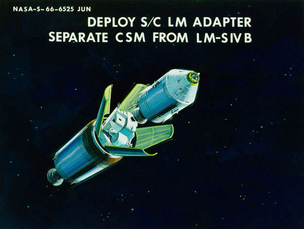
Figure 26
Having received the decision to proceed with transposition and docking, the Command and Service Modules separate from the S-IVB/LM combination using the SM Reaction Control System. This separation severs the hardline control interface between the crew and the S-IVB; any further maneuvers of the S-IVB will need to come from the ground command. However, the orientation selected before separation was one which will not require any adjustments - at least for the first hour, during which transposition and docking will normally be completed. Present plans are to place the vehicle in an inertial attitude hold mode before separation, oriented so that the launch vehicle directional antenna continues to see the ground station as the spacecraft trajectory sweeps through about 45 degrees of central angle during the next 45 minutes. During this period the S-IVB directional antenna has been switched to its narrow beam, but communications are maintained. During the second hour of the transposition and docking phase, which is provided for contingencies, it may be necessary to reorient the S-IVB (from the ground) to maintain communications with the launch vehicle. Returning to the transposition and docking sequence, Figure 26 illustrates the separation of the CSM from the S-IVB-LM. The adapter panels are deployed as part of the separation sequence and are held at a 45° angle with respect to the longitudinal axis. This is sufficient to clear the LM and allow a clean ex¬traction maneuver. If the petals are folded back completely, then they shroud the S-IVB antennas located around the periphery of the Instrument Unit.
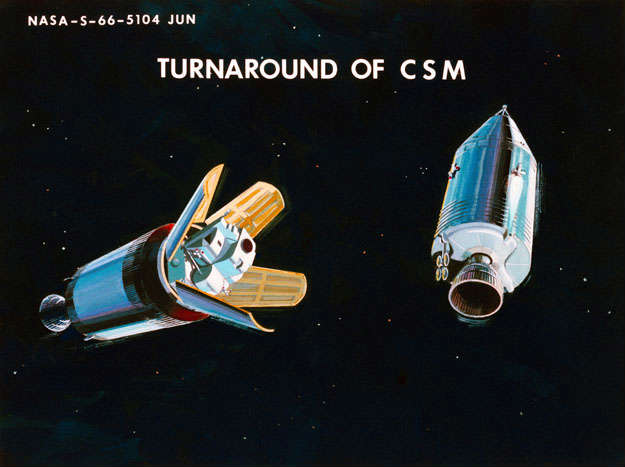
Figure 27
The Service Module RCS is used to translate some 100 feet away from the S-IVB. At this point, the translation is stopped and the CSM is rolled to the proper indexing for docking and then pitched 180° so that it is pointing back at the LM (Figure 27). The roll-pitch sequence rather than a pitch-roll sequence is used to avoid placing the spacecraft omni antenna null zone at the MSFN station during the l80° pitch maneuver. In the case of the spacecraft, yaw maneuvers must be restricted to less than ±70° to avoid gimbal lock. Unlike maneuvers during the rest of the mission, the turnaround is done at the rapid rate of 5 degrees per second in order to reduce the time required for transposition and docking; and, in particular, to minimize the time the crew is out of line of sight of the launch vehicle in the separated condition.
Having turned around, the crew will now deploy the spacecraft high gain steerable antenna and orient it to earth before closing on the LM for docking. This is required because the spacecraft omni antennas will be blanketed by the adapter petals once the CSM gets in close to the LM for docking; therefore, communications with the ground will have to be maintained using the high-gain antenna.

Figure 28
The docking operation continues under the manual control of the spacecraft crew as the final translation is made and the CSM slowly closes on the LM/S-IVB. Initial contact is made when the docking probe on the CM engages the drogue mounted on the LM; the docking mechanism pulls the two vehicles firmly together the final few inches, four latches automatically engage, and the initial soft docking is completed (Figure 28). The next step will be to manually hook up the CM-LM umbilicals, and complete the latching operation by manually engaging 8 more latches. The functions of the umbilicals are twofold: first to supply the hardline connection between the CM controls and the explosive ties, which attach the LM to the adapter. These ties will be severed by crew command when they get ready to withdraw the LM. The other function of the umbilicals is to supply a small electrical power level to certain LM equipment from the CSM power source during the translunar coast phase of the mission. The chief user of this power are small heaters in the LM IMU which needs to be maintained within narrow temperature limits at all times. This permits use of smaller batteries in the LM than would otherwise be required, so the LM will remain inactive for most of the translunar phase. The operations during the docked period prior to separation will require about 20 minutes and will, of course, necessitate one of the crewmen leaving his couch and moving to the area of the docking tunnel. There is less inherent radiation protection from equipment and storage in the tunnel area for the crew; however, these operations do not require the crewman to be in this area for very long, and, further, this period coincides with the pas¬sage between the inner and outer radiation belts where the radiation level is lowest. Hence, there are no radiation constraints as a result of this operation.


Figure 29
A schematic representation of the docking indexing is shown in Figure 29. The CSM-LM axes are offset by 60°. This allows the CM pilot to line up on the docking target located on the LM. Similarly, when docking in lunar orbit, this indexing will allow the LM pilot to see the docking target mounted in the CM right hand window. Also shown in the diagram is the CSM high gain antenna which, unless the pitch attitude is properly selected, will be shrouded by the adapter panels. The S-IVB high gain antenna is located in this same quadrant (along the -Z axis of LM).
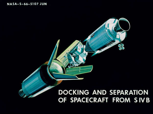
Figure 30
After completion of hard docking, the LM attachment ties are severed, and the LM is extracted from the adapter using the SM RCS system to back away (Figure 30). Approximately 3 ft/sec. separation velocity is applied by the RCS which is sufficiently high to virtually assure no problem of subsequent recontact with the S-IVB.
It would be well here to point out a general characteristic of the Apollo spacecraft - namely, its large radius of gyration in pitch and yaw, its small value in roll. This being the lunar vehicle, it is not close coupled as Mercury and Gemini, except in roll.
One deg/sec. rate costs 11 lbs. in pitch and yaw and 1 lb. in roll (to start and stop). The 5°/sec rate referred to earlier, then, cost about 50 lbs. This is a large price to pay for that simple maneuver, but experience indicates that long periods remote from the station-keeping target should be avoided. It is illustrative of the cost per maneuver. This cost leads us to pre-planned maneuvers to take advantage of the low inertia in roll and to think through each maneuver to minimize propellant consumption. This frugal use of RCS reactant is mandatory until the possible requirement for LM rescue in lunar orbit has passed. At this point the spacecraft is about one hour past the translunar injection point at an altitude of about 9,000 nautical miles. Inertial velocity has decreased to about 23,000 ft/sec. or about 13,000 ft/sec. less than we had at injection cutoff. The velocity will, of course, continue to decrease for most of the trip until the spacecraft nears the moon.
The spacecraft is now being tracked by one of the three deep space stations with 85 ft. dishes (Madrid, Canberra, or Goldstone), and two of the unified S-band stations with 35 ft. dishes. Similar tracking coverage will be available throughout the rest of the mission back to entry, except for periods when the spacecraft is behind the moon.
The first midcourse correction will be made in about two hours, after the spacecraft's trajectory has been accurately determined by extensive ground tracking. During this period, the crew will make a series of star-landmark sightings to check out their space mode of navigation, which is a backup to the ground navigation.
The time of the first midcourse correction is not a critical event. Delaying the correction will, of course, allow the initial injection errors to grow, so that a larger delta V will be required for the injection correction once it is made; however, it is not extremely sensitive in the range of 3 to 5 hours after injection. In some cases, it will even be preferred to wait; if the injection has been particularly good, the delta V required for the early correction may be so low that it could not be performed accurately with the 20,000 lbs. thrust SPS engine (less than about 4 ft/sec). Such small corrections could be made with the SM RCS engines but it would be preferred to conserve RCS propellant wherever possible, even at the expense of SPS propellant, where the reserves are considerably greater.
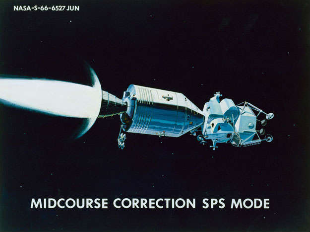
Figure 31
The typical midcourse correction, then, will be done with the SPS (Figure 3l) about three hours after translunar injection, and will require a delta V of about 25 ft/sec., based on analyses of expected injection accuracies. This corresponds to about 3 seconds burn time by the SPS, and could occur in any direction.
Following the midcourse correction, the spacecraft is set up for the long coast period ahead. Another correction is not expected to be required until the spacecraft nears the moon, about 2 days later.
The first operation to be performed is to orient the spacecraft for passive thermal control. The object of passive thermal control is, of course, to insure that critical components in the spacecraft do not get too hot or too cold during the long coast period, as a result of either looking directly at the sun or directly away from the sun for long periods of time. For example, the SM-RCS propellant valves are located adjacent to the SM skin, and their temperature is relatively sensitive to spacecraft orientation (even though they are insulated). Heaters are provided for the valves to accommodate the unavoidable thermal cycling experienced in lunar orbit, but the use of passive thermal control during the translunar and transearth coast phases, allows conservation of electrical energy which would otherwise be required for heater operation. More important, however, the use of passive thermal control negates the necessity for an active coolant loop to cool these same sensitive components.
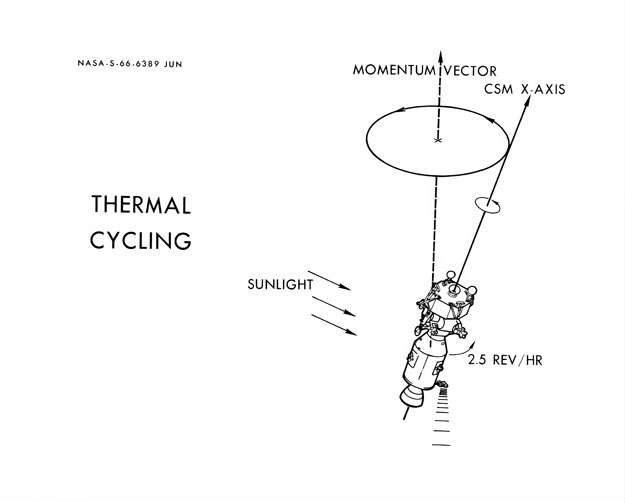
Figure 32
Passive thermal control is usually referred to by the less technical, but more descriptive, term of "barbequing". The orientation maneuver is made such that the spacecraft longitudinal axis is placed perpendicular to the vehicle-sun line (figure 32). The orientation of the longitudinal axis about the sun vector is chosen to minimize the interference of the subsequent roll maneuver with high gain antenna coverage. After stabilizing the spacecraft in this orientation, a slow rotational rate about the X-axis is established to achieve the desired thermal cycling.
As a result of small residual rates about all these axes when the spacecraft was "stabilized", and as a result of other sources of disturbances such as fuel slosh and steam venting, the vehicle will begin slowly to precess about its angular momentum vector. Current analysis indicate that a roll rate of about 2.5 revolutions per hour will be required in order to maintain the spacecraft YZ plane within 20° of the sun line, which is the tolerance required to maintain effective thermal control.
It is emphasized that the thermal cycling operation can be interrupted for periods of up to three hours, provided these attitude hold periods are followed by an appropriate period of barbequing (5 to 7 times the hold period). In addition, the thermal design is such that a three hour period prior to lunar orbit insertion and prior to entry can be accommodated without the necessity of subsequent thermal cycling.
Following the establishment of the barbeque mode, operations onboard the spacecraft will settle down to a routine for the next 2.5 days. Periodic systems status checks will be performed by the crew, the spacecraft's position and velocity will continue to be monitored by the ground, and data will be transmitted continuously by the spacecraft. For the sun's position such as to give us a 7 to 20 elevation angle at lunar landing, the passive thermal control maneuver can usually be set up such as to provide continuous coverage of the ground station with the high-gain antenna during the translunar coast phase (except for sites west of about 20° W longitude). This will not be the case for the transearth coast phase, but the situation is not considered to be a problem since the ground station (because of its higher radiative power) will always be able to contact the spacecraft over the omni antennas, and request that the roll maneuver be discontinued for a period, if continuous communications were required for some reason.
A second midcourse correction will be made about one hour after entering the moon's sphere of influence, several hours before reaching lunar orbit. It is executed with the SPS in the same manner described previously.
Following another rest period, the crew begins a period of considerable activity which will continue for the next several hours through lunar landing and the first exploration period. These activities will be discussed in detail in a later paper by Mr. Loftus, but the highlights will be mentioned here.
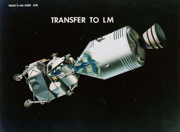
Figure 33
About three hours before lunar orbit insertion, the LM will be checked out. After pressurizing the LM, which has leaked down during the long coast period, one of the three crew members will transfer to the LM through the tunnel and begin an activation and checkout of the LM systems (figure 33). This is considered desirable for two reasons: First, it provides the ground and the crew with the first knowledge since leaving the launch pad that the LM systems will indeed be able to function properly for a lunar landing. The discovery of some system malfunction which would preclude lunar landing may be sufficient reason not to commit the mission to lunar orbit.
The second reason for LM checkout prior to lunar orbit is to assure that the descent propulsion system is available as a ready means of abort in the event of SPS failure during lunar orbit insertion. Since the abort mode using the descent propulsion system also requires the use of the LM guidance and control system, it will be necessary to activate, checkout and align this system also. Similarly, the Environmental Control and Electrical Power Systems will need to be activated. A second crewman will join the first when freedom from his duties in the CM permits.
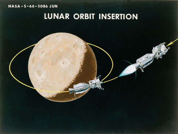
Figure 34
Continuous ground tracking confirms that the spacecraft is indeed on the proper course and the decision is made to proceed to lunar orbit insertion. The LM crew has returned to the CM by this time and the next operation is to orient for lunar orbit insertion and prepare the spacecraft for SPS thrusting. A few minutes later, sunset occurs and shortly thereafter the space¬craft passes out of earth line of sight. Three or four minutes later, SPS ignition occurs for lunar orbit insertion (figure 34).
LUNAR ORBIT INSERTION
The spacecraft altitude at this point is typically 150 nautical miles. Burn duration for the lunar orbit insertion is typically somewhat over six minutes, for a delta V of 3200 ft/sec. Corresponding SPS propellant for this maneuver is about 24,000 lbs. During the insertion maneuver the spacecraft has travelled through a central angle of about 20º, and ends up in a circular orbit of 80 nautical miles altitude. During the insertion, a plane change was executed to make the orbit inclination such that the spacecraft orbit passes over the intended landing site on the third revolution. This situation allows an in-plane descent with the LM on this third pass.
LUNAR ORBIT COAST PRE-SEPARATION

Figure 35
The spacecraft is now on another plateau, lunar orbit coast (figure 35). The CSM and LM will remain in the attached condition in lunar orbit for the next 5.5 hours (figure 36). During this time, three passes over the front side of the moon will have been made, and the spacecraft will have been tracked by the earth on each pass. This will have been more than sufficient to accurately determine the lunar orbit parameters. In order to reduce the uncertainties in the selenographic position and altitude of the landing site, and to enhance confidence, a series of onboard landmark sightings in the vicinity of the landing site will be made during two of these passes. This point will be discussed in more detail in the paper by Mr. Cheatham.
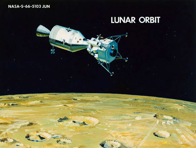
Figure 36
Communications with earth and data transmission will have been maintained on each pass in front of the moon. During periods when the spacecraft is behind the moon, data is recorded onboard for subsequent playback when line of sight is reacquired.
Additional operations during this period will involve the crew going back into the LM, and activating and checking out those systems not checked out before lunar orbit insertion. After transferring certain equipment to be used on the lunar surface from the CM to the LM, the LM platform is aligned, information in the CM computer is transferred to the LM computer, the hatches are closed, and preparation is made for separation.
CSM/LM SEPARATION
Separation is performed by the LM RCS system (5 seconds burn) about 30 minutes prior to the actual time of LM transfer orbit insertion. The separation delta V is small, about 1 ft/sec, so that the two vehicles drift apart very gradually (figure 37). When the vehicles are about 60 feet apart, the LM will pitch up to an attitude which allows the CM crewman visually to inspect (with the sextant) the external portion of the LM including the landing gear and probes.
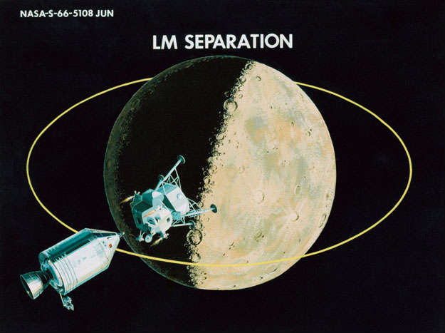
Figure 37
A few minutes later the vehicles are far enough apart to perform a checkout of the LM rendezvous radar and CSM transponder. Also, during this separated period, the LM platform is fine aligned, the controls and displays are checked out in the LM-alone configuration, and preparations are made for transfer orbit insertion.
Before the LM passed out of line of sight of earth, data transmission and voice communications had been maintained directly using the LM S-band high gain antenna. After losing line of sight, the LM data will be transmitted to the CSM where it is recorded for subsequent playback. This will be the situation during all phases when the LM is behind the moon, since it carries no onboard data recorder of its own.
The separation maneuver was made in such a direction as to place the LM ahead and below the CSM throughout the 30 minutes coast period to the transfer orbit insertion point. This type of separation maneuver avoids the possibility of jet impingement or collision during the transfer burn by increasing the LM/CSM range (for a small delta V) as compared to the forward or rearward separation methods. Another advantage is that it provides clear VHF communications between CSM and LM during the coast and during the transfer maneuver. The two vehicles are about one-quarter mile apart at the time of transfer orbit insertion.
TRANSFER ORBIT INSERTION
Prior to the engine burn, propellant settling is provided by a five second RCS firing of the four X-axis thrusters.
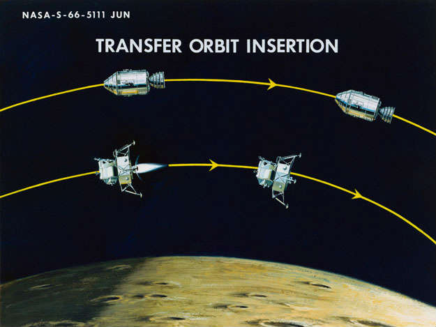
Figure 38
The insertion maneuver takes place behind the moon about 200º central angle from the landing site (figure 38). Descent engine thrust is maintained at 30% for the first three seconds and is then reduced to 10% for the next 23 seconds and is then increased to 92.5% thrust (9700 lbs.) for the final six seconds of burn. The period at low thrust is required due to the possibility that the vehicle's center of gravity deviates from its nominal location and that the engine thrust vector is not acting through the c.g. Since the engine gimbals are used for trim control only and are relatively slow, the engine thrust is reduced to insure that the moment control of the RCS is not exceeded during the initial travel. The high thrust at the end of the burn allows a check to be made on the engine through its full throttling range.
The fuel expended during the insertion maneuver is about 330 lbs., and the corresponding delta V is slightly less than 100 ft/sec.
COASTING DESCENT

Figure 39
The spacecraft is now on the next plateau, descent coast (figure 39). At this point, the LM is on a slowly descending trajectory which will continue for about the next hour until it reaches its pericynthion altitude of 50,000 ft. During this period, the LM will track the CSM with its Rendezvous Radar and determine its descent trajectory onboard. Similarly, the CM can track the LM flashing light with its sextant and perform an independent determination of the LM orbit. Finally, when the LM comes within line of sight of earth, then the ground station will track the vehicle and provide the LM with the final source of navigation data. As in all operations discussed up to this point, the ground based navigation is the primary source of data.
If the decision is made not to initiate powered descent, the LM is in a safe orbit from which it could subsequently rendezvous with the CSM, or if necessary, the CSM could perform a rescue. Having decided to continue descent, however, another IMU alignment will be made and preparations for powered descent begin. Up to this point in the coasting descent, the LM has been leading the CSM. At pericynthion, this lead angle is about 10 degrees. From this point on, however, once the LM begins powered descent, the CSM will catch up and finally go ahead of the LM during the latter part of the landing maneuver.
POWERED DESCENT
At the 50,000 ft. pericynthion altitude, a propellant settling maneuver is performed with a 5-second RCS firing, followed by descent engine ignition. The thrust profile is the same as before with a 3-second burn at 30% thrust, followed by a 28-second period at 10% thrust, and then increased to 92.5% thrust (9700 lbs.). The powered descent phase will be discussed in detail in a later presentation by Mr. Cheatham, so only the gross profile will be described here.
The powered descent is divided into three distinct portions, called the braking phase, the final approach phase, and the landing phase.
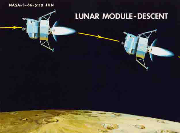
Figure 40
Phase I, the braking phase is designed primarily for efficient reduction of the orbital velocity and is therefore performed at maximum thrust with near horizontal flight path angles (figure 40). It is the longest of the three phases - lasting almost 8 minutes while covering almost 250 miles, down to an altitude of about 8600 feet.
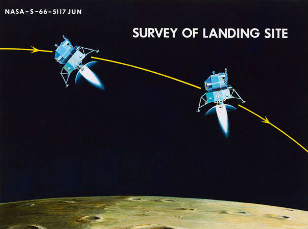
Figure 41
Phase II, the final approach phase, begins at the 8600 ft. point, called "high gate", about 8 nautical miles range from the landing site. It begins with a pitch maneuver which brings the horizon and the landing site into the pilot's view for the first time (figure 41). The purpose of this phase is to provide the crew time to assess the trajectory as the LM approaches the surface, to provide the crew the opportunity to assess the landing area, and to allow for pilot takeover of the control tasks if required. The throttle is reduced back to 60% thrust during this phase. Duration of this phase is somewhat less than 1½ minutes. Forward velocity is reduced from about 450 ft/sec. at the beginning to about 50 ft/sec at the end. Altitude is 500 ft. at the end of the final approach and the range to the landing site is about 1200 ft.
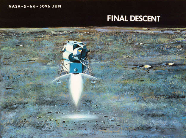
Figure 42
Phase III, the landing phase, is designed specifically for pilot control and provides the capability for making a detailed assessment of the landing site. The vehicle is pitched back to a near vertical attitude, the thrust is reduced, vertical and horizontal velocities are reduced, and a vertical descent is made from the last 100 ft. altitude (figures 42 and 43). Duration of this phase is nominally about 75 seconds, but the capability exists to extend it longer if more landing site assessment time or small redesignations are required.
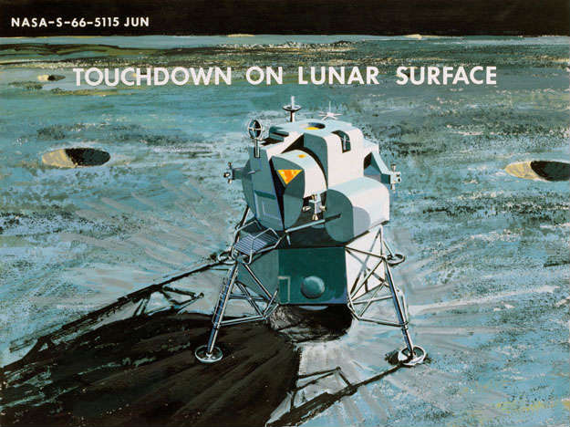
Figure 43
Fuel used during the entire powered descent is around 16,000 lbs. corresponding to a delta V of about 6600 ft/sec.
LUNAR SURFACE STAY

Figure 44
At this point, the spacecraft is on the next plateau, lunar stay (figure 44). Following an assessment of the vehicle situation to determine if there is a necessity for an early abort, the postlanding checkout is begun. The descent engine is disarmed and the descent propellant tanks are vented. The IMU is aligned and placed on standby operation. Systems not required during the lunar surface stay are shut down.
Following a period of coordination with the ground, a thorough check out of the Extravehicular Mobility Unit is performed, an EMU is donned by each crewman and preparations are made for egress. Life support is switched to the Portable Life Support System, the cabin is depressurized, and the forward hatch opened. This occurs about 1.75 hours after landing. The lunar surface stay time on the first mission is planned for approximately l8 hours (figure 45). During this time, two 3-hour exploration periods are provided for each astronaut to be done simultaneously - for a total of 12 man-hours of lunar surface activity. The scientific objectives and activities will be the subject of a later paper, but the general activities will be described here.
Apollo 11 - EVA started some 7 hours after landing for just 2.5 hours lunar surface stay - 21 hours
The initial portion of the first exploration will be occupied with a general external inspection of the vehicle. Measurements will be made of the landing gear stroke, depression made by the pads, any evidence of sliding will be noted, etc., for the kind of engineering measurements that might be helpful for future landings. This will require about one-half hour. During this time, the second astronaut has stationed himself on the forward boarding platform and is making a detailed description and photographic record of the lunar terrain from his vantage point. Both astronauts are in voice contact with the ground during this period.
The next step will involve unloading equipment, including the Lunar Surface Experiments Package from the descent stage storage bay. The lunar surface erectable high gain antenna will be set up so that continued data transmission from the LM can take place at a lower power. Television pictures can be transmitted during this exploration as time permits.
In keeping with the stated scientific priorities, the first scientific task will be to gather lunar samples. One of the two specimen return containers will be filled during this first exploration, and stored in the LM cabin at the end. This insures that at least part of the scientific objectives will be met in the event some malfunction prevented a second exploration period.
If time permits, and if the work load has not been excessive, then one of the astronauts can begin the LSEP deployment, while the other collects lunar samples in the same vicinity. The actual LSEP deployment will be discussed in a later paper by Mr. Vale.
At the end of the first exploration the two crewmen return to the LM, pressurize the cabin and remove the EMU. One of the PLSS units is put on recharge while the crew has a meal, and the other is recharging during the 6 hour sleep period which follows. Following the 6 hour sleep period, the crew will have another meal, check and don the EMU, and prepare for the second exploration period. During the second exploration, the LSEP will be deployed, and a more selective collection of lunar samples will be made, filling the second specimen return container. The astronauts will be able to range somewhat further from the landing site on this exploration.
During the period that the LM is on the lunar surface, the astronaut in the CM performs periodic systems checks of the CSM systems, and maintains communications directly with earth and indirectly with LM over the earth relay link.
Returning to the LM, following the last exploration period, the
prelaunch checkout is conducted wherein all systems are activated, checked
out, and prepared for launch. The Rendezvous Radar will have been checked
by tracking the CSM on its previous pass over the landing site prior to
launch.
LUNAR ASCENT
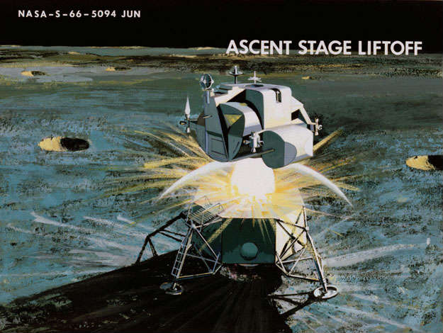
Figure 46
Ascent engine ignition will occur at the beginning of the 3.5 minute launch window when the CSM leads the LM by about 10 degrees (figure 46). The ascent engine propellant tanks are pressurized, propellant valves are opened, and the structural ties and umbilical between the descent and ascent stage are severed by explosive charges.
Following a 12 second vertical rise period, the guidance system commands the LM attitude to an optimum profile designed to boost the vehicle to orbital velocity. The ascent engine has a fixed thrust of 3500 lbs., and is non-gimbaled, so moment control must be provided by the RCS engines. The main ascent trajectory is a standard one which ends at 50,000 ft. altitude with a slight overspeed such that the resultant coast trajectory is an ellipse with about a 30 nautical mile apocynthion and a 50,000 ft. pericynthion. Hence, at the end of the main ascent, the LM is on a safe trajectory, or plateau, which will not impact the moon even if the subsequent burns are not performed (figure 47). That is, it is in a relatively stable situation from which a rescue by the CSM could be performed, if necessary.

Figure 47
The main ascent burn is typically of 6.5 minutes duration during which about 4,800 lbs. of propellant is consumed. Delta V is typically about 6000 ft/sec. The ascent maneuvers are illustrated in figure 48.

Figure 48
Following the engine shutdown, the LM acquires and tracks the CSM with the Rendezvous Radar to determine its orbit. At this point, the CSM is still leading the LM and is about 350 miles away. The ground has been tracking the LM during the entire ascent and continues to do so. Based on this tracking, a determination will be made of the next maneuver to be performed some thirty minutes after beginning of coast.
This next maneuver is called the concentric sequence initiation or CSI. It is a relatively small maneuver made with the RCS jets, and is designed to raise the pericynthion of the LM orbit to an altitude consistent with that required for proper phasing with the SM. At the same time, it is somewhat like a midcourse correction in that it will be calculated to absorb the trajectory dispersions resulting from the main ascent. For an on-time launch (beginning of launch window) the pericynthion altitude will be raised to 65 n. miles with the CSI maneuver. This will require about 60 ft/sec. delta V, consuming about 40 lbs. of RCS propellant; burn time for the two RCS thrusters would be about 50 seconds. If launch had not occurred until the end of the launch window, then the proper phasing altitude would have been 30 n. miles, so no CSI maneuver would have been required in this case, except as a small correction to absorb the launch dispersions.
Depending on the landing site longitude, line of sight to the earth has probably been lost by this time. The LM to CSM range has been reduced to slightly less that 200 n. miles at the CSI point, with the CSM leading. The LM continues to track the CSM with the Rendezvous Radar and preparations are made for the next step in the ascent sequence which will occur when the LM reaches the high point in its new orbit about 50 minutes after CSI. Blip in the tape 45:58 At this point, another maneuver is made which circularizes the LM orbit at 65 n. miles (for the on-time launch case), such that the LM and CSM orbits are concentric and separated by an altitude of 15 n. miles.
Actual range to the CSM is about 50 n. miles at this point. The circularization maneuver uses about 45 lbs. of RCS propellant with a corresponding delta V of 65 ft/sec. Burn duration is about one minute.
Following the circularization maneuver the LM continues to track the CSM and shortly emerges from behind the moon, at which time tracking from the ground station is resumed.
Based on the LM onboard tracking and the ground based tracking, the conditions are determined for the next maneuver, called the terminal phase initiation or TPI. This maneuver is made about 20 to 30 minutes from the time circularization occurs and is designed to place the LM on an intercept trajectory with the CSM about 140° away from the initiation.
The range to the CSM is about 30 n. miles at the initiation of the transfer maneuver. The transfer burn is made with the RCS jets and amounts to about 23 ft/sec; 15 lbs. of propel¬lant are consumed and burn duration is about 20 seconds.
Following the burn, tracking is performed both on-board and by the ground, and based on this information, a small mid-course correction will be made about 10 to 15 minutes after the initial burn.
During the next 35 minutes, the range to the CSM will be reduced from 30 n. miles to about 3 n. miles, and the range rate to the CSM will be reduced from about 130 ft/sec. to about 30 ft/sec.
A series of range - range rate gates are specified such that (l) at the 3 n. mile point an RCS burn reduces the range rate to 20 ft/sec; (2) at 1 n. mile range a short burn reduces the range rate to 10 ft/sec; and (3) at 500 ft. the rate is reduced to 5 ft/sec. These burns are all in the range of 4 to 8 sec. and consume a total of about 20 lbs. of propellant.
DOCKING
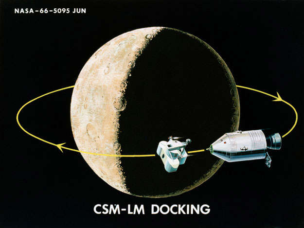
Figure 49
Having passed this last gate, the vehicles are in close proximity at a low relative velocity, and the manual docking phase begins (figure 49). The capability exists for docking in darkness, (lights are provided on-board and the docking target is luminescent); however, in most cases, it will be preferred to wait a few minutes until the vehicles come into sunlight. The relative rates of the two vehicles will be nulled until this time.
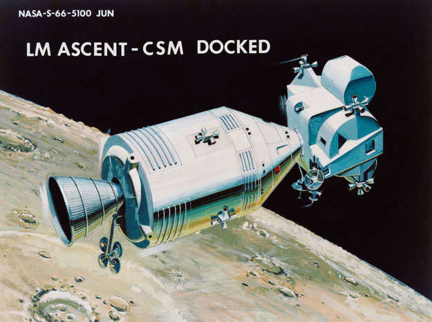
Figure 50
At a range of about 50 ft., the LEM will be pitched back so that the CM
becomes visible in the overhead window. The pilot then translates toward
the CSM at a low rate and engages the CM probe in the LEM drogue. The
docking tunnel is pressurized, the upper hatches are removed, and the
docking latches secured (figure 50).
LUNAR ORBIT COAST AFTER DOCKING

Figure 51
The spacecraft is now on another plateau (Figure 51), and the capability exists to remain on this plateau for an extended period if desired. However, the mission will normally proceed on to the next commit point within a few hours.
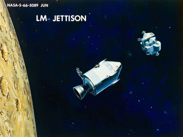
Figure 52
During the next hour or so, the LM is deactivated, the crew and equipment are transferred to the CSM, and finally the LM is jettisoned by firing a shaped charge which separates the CM and LM, and the CSM translates away with the SM-RCS (figure 52).
The first opportunity for transearth injection will occur in about one
hour, but injection will not normally be planned for this first
opportunity, since systems readiness checks, exchange of data with the
earth, and IMU alignment have yet to be performed. So the spacecraft
continues in lunar orbit for one more revolution before transearth
injection.
TRANSEARTH INJECTION
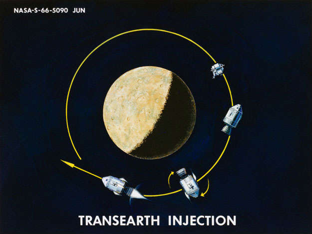
Figure 53
Transearth injection occurs on the back side of the moon with respect to the earth, and will normally be in the dark. The SPS burn is preceded by a 14 second ullage burn from the SM-RCS to settle the propellants. This ullage maneuver was not required on the previous SPS burns on the way to the moon since the tanks were essentially full, but now they are only about one-third full. (Figure 53)
Transearth injection delta V will vary from about 2600 ft/sec. to about 3200 ft/sec. depending on whether the return trajectory is a relatively slow (110 hr.) or a relatively fast (86 hr.) transfer. The 24 hour flexibility is necessary to allow a return to the primary recovery area on earth (in the vicinity of Hawaii) from any mission.
A typical value for propellant consumed during transearth injection is about 8000 lbs. with an SPS burn time of about 2 minutes.
52:20
TRANSEARTH COAST
Soon after the end of the burn, the spacecraft comes within line of sight of earth and continuous tracking begins. Data recorded on board the CSM during the injection burn is played back to the ground station, the CSM is powered down, the passive thermal control maneuver is initiated, and the crew goes to sleep. The spacecraft is now on another mission plateau, transearth coast (figures 54 and 55).

Figure 54
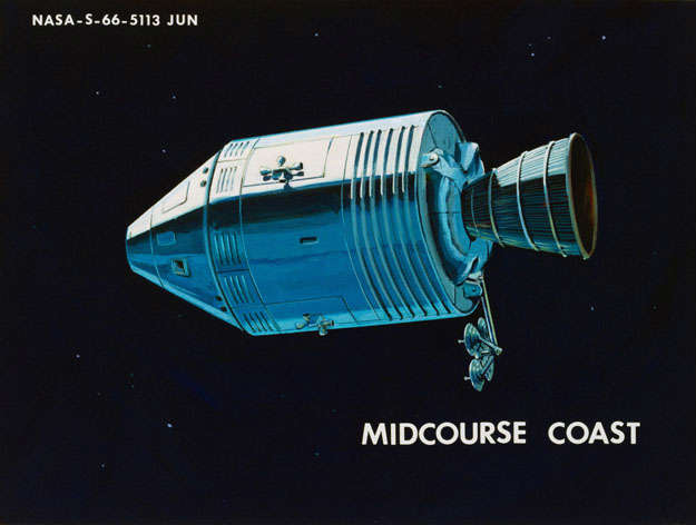
Figure 55
Operations during the transearth coast phase are similar to those described during translunar coast, with few notable exceptions:
First, the position of the sun relative to the transearth trajectory will be such as to result in hi-gain antenna communications loss during each revolution of the thermal cycling maneuver. Typical values for a 2.5 revolution per hour roll rate would be loss of earth for 4 minutes out of every 24 minute revolution. As mentioned in the previous discussion, this is not considered a problem, since the ground can contact the spacecraft at any time and request that a communications attitude be held. Also, it is likely that voice and low bit rate telemetry can be maintained over the omni-antennas for much of the transearth phase.
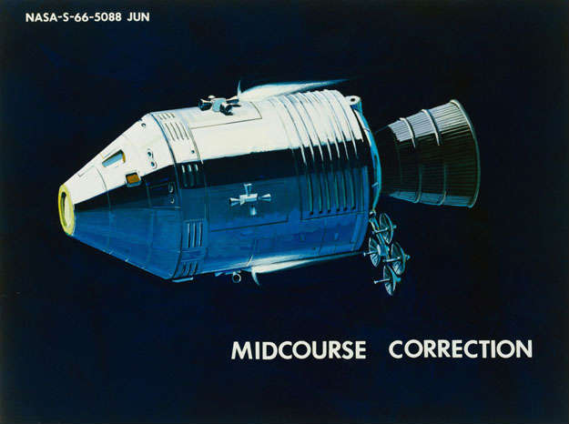
Figure 56
The other major difference from the translunar phase concerns the midcourse corrections. In this case, it is almost certain that the corrections will need to be made with the SM-RCS. The spacecraft is considerably lighter now, but the minimum impulse capability is the same, so that the minimum delta V which can be performed with the SPS is 12 ft/sec; the addition of 5 ft/sec. to this value for the ullage maneuver results in the fact that the midcourse correction must be at least 17 ft/sec. before it can be performed with the SPS. Error analysis of the MSFN tracking capability and the SPS cut off errors indicate that the corrections will be considerably less than 17 ft/sec; hence, the plan will be to perform these corrections with the SM-RCS (figure 56). As in the translunar case, two corrections will probably suffice: the first about 10 hours after injection and the second about 2 hours before entry.
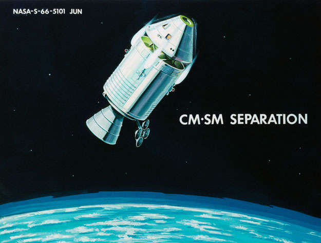
Figure 57
About 15 minutes prior to the entry interface (400,000 ft.) the SM is jettisoned when the spacecraft is some 2500 nautical miles from earth (figure 57). The spacecraft is oriented for SM jettison in such a way that the 3.5 ft/sec. separation velocity applied by the SM RCS jets places it on a path which minimizes the probability of subsequent recontact with the CM. The CM is then oriented to the entry attitude using its own RCS jets (figure 58).
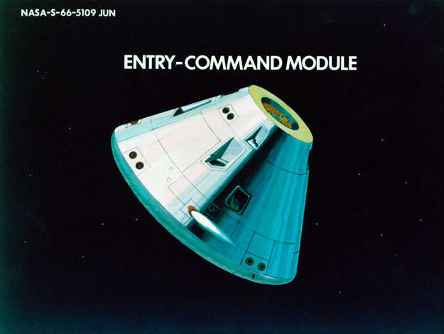
Figure 58
ENTRY
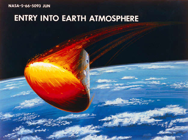
Figure 59
Entry will normally begin over the western Pacific at about 400,000 ft. altitude. Range from this point to splashdown will be from 1500 to 2500 n. miles, and it will be controlled by varying the direction and time application of the space¬craft lift (figure 59).
A ground based station at Guam or in Australia, depending on the
inclination of the approach path, will track the spacecraft just prior to
entry, but the entry phase itself will normally not be in line of sight of
a ground based station. Tracking during entry will be provided by two
ships positioned along the entry path. This insures that tracking is
continuous during this period, except possibly during the blackout period.
EARTH LANDING PHASE
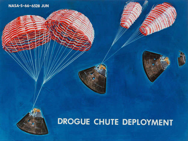
Figure 60
The earth landing sequence begins at 24,000 ft. The forward heat shield is jettisoned, which exposes the CM bay where the parachutes are stored. The two drogue chutes are deployed immediately thereafter and are disreefed a few seconds later (figure 60). The drogue chutes serve to orient the CM properly for main chute deployment, and reduce the velocity from about 400 ft/sec. at deployment to about 200 ft/sec. at 10,000 ft. altitude where the main chutes are deployed.
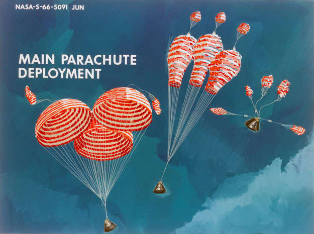
Figure 61
Three pilot chutes pull out the three main chutes and the drogue chutes are disconnected (figure 6l). A few seconds later, the main chutes are disreefed and the descent rate is reduced to about 25 ft./sec. at splashdown.
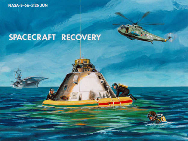
Figure 62
Recovery is soon effected and the crew and spacecraft are taken aboard ship (figure 62).
DELTA VELOCITY BUDGET AND SPACECRAFT WEIGHTS
In the previous sections concerning the mission description, there were many references to the delta V and propellant requirements for the various propulsive maneuvers during the lunar landing mission. It will be of interest at this point briefly to summarize the overall delta V budget and spacecraft weight data currently being considered for the mission.
Hiçbir yazı/ resim izinsiz olarak kullanılamaz!! Telif hakları uyarınca bu bir suçtur..! Tüm hakları Çetin BAL' a aittir. Kaynak gösterilmek şartıyla siteden alıntı yapılabilir.
© 1998 Cetin BAL - GSM:+90 05366063183 -Turkiye/Denizli
Ana Sayfa / Index / Roket bilimi / E-Mail / Rölativite Dosyası
Time Travel Technology / UFO Galerisi / UFO Technology /
Kuantum Teleportation / Kuantum Fizigi / Uçaklar(Aeroplane)
New World Order(Macro Philosophy) / Astronomy