Rocket Engine


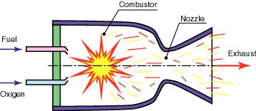
Schematic of a liquid rocket engine
A rocket engine differs from a jet engine primarily in one key way. Whereas the jet pulls in oxidizer from the atmosphere, a rocket carries its own supply of oxygen aboard the vehicle. An example shown below is the liquid rocket engine. This class of rocket carries a liquid fuel and a liquid oxidizer in two separate tanks. The two liquids are pumped into a combustion chamber at some rate, called the mass flow rate, where they are mixed and burned. Just as in the jet engine described earlier, this combustion process generates a high-pressure gas that is exhausted through a nozzle to generate thrust.

Even though the Chinese introduced rockets about 800 years ago, most of
the important rocket development has taken place in the 20th Century. A
rocket engine is the component that makes travel at top velocities
possible and it is fueled through high-pressure movement of propellant
material according to certain laws of physics – namely Isaac Newton’s
Third Law of Motion. Rocket engines have structures that give them
advantages over other types of engines and scientists are frequently
applying technological improvements to them.

Simple Liquid Rocket Schematic
Liquid propellant rocket engines
Liquid propellant rocket engines use a liquid fuel (such as liquid hydrogen or kerosene) and liquid oxidiser (such as liquid oxygen). These are stored in separate tanks and then pumped into the combustion chamber as required. As they are sprayed into the combustion chamber through injection nozzles, they rapidly mix together and react before being ejected.
One advantage of a liquid fuel system is that the amount of thrust can be controlled. This is done by limiting how quickly the fuel is pumped into the combustion chamber.

The three main engines on the tail of the Space Shuttle orbiter are liquid fuel rocket engines. The external tank (ET) is the big orange tank and contains two separate storage tanks – one containing liquid hydrogen and one containing liquid oxygen.
The hydrogen and oxygen are pumped to the three main engines. They are sprayed into a combustion chamber where the hydrogen reacts with the oxygen to form gaseous water. It is the high-speed ejection of this gaseous water that produces the thrust.
Each main engine produces a thrust of 1.8 MN (1.8 million N). It does this by reacting 1340 litres of propellant each second and ejecting the gaseous water at a speed of 3560 m/s (12 800 km/h).
Rocket:

The rocket engine is the simplest of this family, so we’ll start there.
In order to work in outer space, rocket engines must carry their own supply of oxygen as well as fuel. The mixture is injected into the combustion chamber where it burns continuously. The high-pressure gas escapes through the nozzle, causing thrust in the opposite direction.

To test this principle yourself, inflate a toy balloon and release it without tying it off…rocket propulsion at its simplest.

Background and Development
The guiding idea behind rocket engine movement is that the exertion
of force must always be between two objects rather than onto a single
object. Newton’s Third Law dictates that the force causing movement
between these objects must be equal in strength in order for the desired
speeds to be reached. Experiments with propulsion of objects according
to this law date back to the first century BC; however, the full
potential for its application to rocket engine technology was not fully
understood until after the Industrial Revolution of the nineteenth
century.
Beginning with the space race between the United States and Russia in
the mid-twentieth century, scientists and engineers applied this law of
physics to modern engine-building in earnest. Each nation had the goal
of sending the fastest, lightest, strongest, and safest spacecraft into
orbit. In the following decades, jet engines built according to these
specifications soon began appearing in other crafts alongside the U.S.
space shuttle – namely military aircraft and missiles.
Structure
The distinction between these types of engines and others is the
structure of the internal combustion engine.
The majority of widely used rocket engines fall into this category, though
a smaller number have been built as non-combustible engines. In order
for an internal combustion engine to operate, it needs to have a supply
of fuel that is ignited by an oxidizing agent. When this occurs, the
extreme pressure that results is forced through one or more nozzles.
This pressure acts as the propelling agent that pushes the rocket
forward at very high rates of velocity.
Function
The pushing of a rocket forward and/or upward is known as thrust, and thrust is the by-product of exhaust created by the fuel supply. In most cases, this supply is from fossil fuels. The energy generated from the fuel’s heat creates quite high speeds as the exhaust is expelled from the rocket nozzles, pushing the rocket in the opposite direction as this exhaust. The flames that are visible from the back of a moving rocket are actually combusted fuel exhaust.
Modern rocket engines need both very high pressures and very hot temperatures to reach the desired speeds, particularly to create what is known as escape velocity in space travel. A rate of velocity higher than the pull of the earth’s gravitational atmosphere is required to reach orbit above the planet.
Chemical Reaction
Rockets with a chemical reactor engine are among the most frequently built and have been designed for fuel use efficiency according to basic thermodynamics. Fuel heated to extreme temperatures is done so through an exothermic reaction, simply meaning one from an external source. In order for this reaction to work correctly, a rocket needs to be fitted with a combustion chamber to allow for the oxidizer to reach the fuel in a controlled area. Other rocket engines without a combustion chamber can still be powered to the required levels using a separate heat exchanger. Use of these different chemical reaction systems often depends on the rocket’s intended purpose.
Additional and notable rocket propulsion systems under development and experimentation include:
- Nuclear/Thermonuclear
- Solar Propulsion
- ION Propulsion
- Plasma

On this slide, we show a schematic of a rocket engine. In a rocket engine, stored fuel and stored oxidizer are ignited in a combustion chamber. The combustion produces great amounts of exhaust gas at high temperature and pressure. The hot exhaust is passed through a nozzle which accelerates the flow. Thrust is produced according to Newton's third law of motion.

Display
model of Blue Origin BE-4 rocket engine at a media briefing at the National
Press Club in Washington, D.C., on Sept. 17, 2014.
The amount of thrust produced by the rocket depends on the mass flow rate
through the engine, the exit velocity of the exhaust, and the pressure at
the nozzle exit. All of these variables depend on the design of the nozzle.
The smallest cross-sectional area of the nozzle is called the throat of the
nozzle. The hot exhaust flow is choked at the throat, which means that the
Mach number is equal to 1.0 in the throat and the mass flow rate m dot is
determined by the throat area. The area ratio from the throat to the exit Ae
sets the exit velocity Ve and the exit pressure pe. You can explore the
design and operation of a rocket nozzle with our interactive thrust
simulator program which runs on your browser.
The exit pressure is only equal to free stream pressure at some design
condition. We must, therefore, use the longer version of the generalized
thrust equation to describe the thrust of the system. If the free stream
pressure is given by p0, the thrust F equation becomes:
F = m dot * Ve + (pe - p0) * Ae
Notice that there is no free stream mass times free stream velocity term in
the thrust equation because no external air is brought on board. Since the
oxidizer is carried on board the rocket, rockets can generate thrust in a
vacuum where there is no other source of oxygen. That's why a rocket will
work in space, where there is no surrounding air, and a gas turbine or
propellor will not work. Turbine engines and propellers rely on the
atmosphere to provide air as the working fluid for propulsion and oxygen in
the air as oxidizer for combustion.

The thrust equation shown above works for both liquid rocket and solid
rocket. engines. There is also an efficiency parameter called the specific
impulse which works for both types of rockets and greatly simplifies the
performance analysis for rockets.

How
Newton powers your Rocket
The primary goal of a rocket engine is to generate thrust. While most people
know what thrust is, many people (including Aerospace Engineers) struggle
with how thrust is actually made. To understand this you have to understand
Newton’s laws of mechanics, specifically the second and third laws:
Second law: The acceleration of a body is directly proportional to, and in
the same direction as, the net force acting on the body, and inversely
proportional to its mass. Thus, F = ma, where F is the net force acting on
the object, m is the mass of the object and a is the acceleration of the
object
Third law: When one body exerts a force on a second body, the second body
simultaneously exerts a force equal in magnitude and opposite in direction
to that of the first body.
These two equations combined are literally what drives the rocket forward.
By throwing mass (propellant) out the back of the engine, the engine
generates a force on the rocket (third law). This force then accelerates the
rocket forward (second law).
Rocket Engine
The rocket engine obtains a combustion gas of high temperature and high
pressure from the fuel and an oxidizer in a conbustor. The combustion gas
becomes high speed with an adiabatic expansion through a nozzle, and is
jetted to the rear of the engine. It is obtained a propulsive force by a
reaction of the high speed gas.
The jet engine and the rocket engine obtains the propulsive force in the
same way by using the reaction of the working gas. However, it is difference
from the jet engine that the rocket engine has the total gas including the
oxidizer itself. Then it can get the propulsive force even if there is no
air, so it is used as the propulsive power source in the space.

How a Rocket Engine Works


- Schematic of Blue Origin BE-4 rocket engine.
A rocket engine is not like a conventional engine. A conventional
engine ignites fuel which then pushes on some pistons, and it turns a
crank. Therefore, it uses rotational energy to turn the wheels of the
vehicle. Electric motors also use rotational energy to turn fans, and
spin disks. A rocket engine does not use rotational energy to run. They
are reaction engines. The principle of it is that the fuel contained
within the body of the rocket goes through a chemical reaction as it comes
out of the end of the rocket. This reaction then causes thrust and
propels the rocket forward. This is an example of one of Sir Isaac
Newton's fundamental laws. "For every action, there is an equal and
opposite reaction" (How Rocket Engines Work.)

Liquid Fuel Rockets
The first liquid fuel rocket was produced by Robert Goddard in 1926 (How
Rocket Engines Work.) The idea of liquid fueled rocket is easy to grasp.
A fuel and an oxidizer ,in Goddards case he used gasoline and liquid
oxygen, are pumped into a combustion chamber. A reaction takes place, and
it expands propelling the rocket forward. The expanding gas is then
forced through a nozzle that makes them accelerate to a higher velocity (How
Rocket Engines Work.)

This diagram is a basic model of how a liquid fuel
rocket engine works.
It is easy to see that a liquid fueled rocket is much more complex that a solid fueled one.
It is easy to see that a liquid fueled rocket is much more complex that a solid fueled one.
How
do rockets work?
As science presenters we are always being asked to take complicated concepts
and simplify them for the audiences we are working with. The process of
simplifying concepts is not an easy one. There is a constant balance to be
struck between ‘dumbing down’ and ‘over-complicating’ whilst trying
remaining ‘accessible’ but ‘correct’. Sometimes it can be impossible.

As an example of the perils of simplification I’ll ask a question. How do
rockets work? Most people would give you the following answer:
Rocket engines work by action and reaction. Rocket engines push rockets
forward simply by throwing their exhaust backwards extremely fast. [Wikipedia:
Rocket]
So is that the answer? Is it as simple as referencing Newton’s Third Law and
being done with it? Well to make it a bit more accessible most people would
then trot out the classic balloon/basketball ‘real-world’ comparison:
When you let the air out of a balloon, the balloon doesn’t just sit there –
it flies around the room. The action is the air rushing out of the balloon,
and the reaction is the balloon being forced in the opposite direction.
Second, imagine you are standing on a skateboard and you throw a football as
hard as you can to your friend. You won’t just sit there – you will roll a
bit in the opposite direction of your throw. The action is your throwing the
football, and the reaction is your movement in the other direction. [Curious
About Astronomy]
So far, so good. Up until a few months ago, I, like most people, would have
left it at that however on a training job in the Middle East this subject
came up*. Someone who I respect and defer to in their scientific knowledge
and experience threw in a totally different explanation- the rocket is
pushed along by an imbalance of pressure:
In a closed [combustion] chamber, the pressures are equal in each direction
and no acceleration occurs. If an opening is provided in the bottom of the
chamber then the pressure is no longer acting on the missing section. This
opening permits the exhaust to escape. The remaining pressures give a
resultant thrust on the side opposite the opening, and these pressures are
what push the rocket along.
We have two competing explanations. Instead of the rocket working by
throwing their exhaust gases backwards this explanation suggests they are
being pushed by an imbalance of pressure. At face value these are totally at
odds with each other. I was certainly very confused to hear this alternate
explanation and it made me (reluctantly*) re-examine my idea of what was
going on.
They are so different is one ‘right’ and one ‘wrong’? Well, no. One seems
more correct than the other but neither actually do a very good job. The
issue here lies with that complication-accessibility/dumb down-correct
dilemma we face as science presenters.
The bald something goes one way so something goes the other explanation,
whilst seeming accessible and simple is not actually very helpful. It
explains what you see- a huge plume of flame going one way and the rocket
going the other- but not what is actually happening. What is it that is
actually making the rocket move? This explanation has been dumbed down too
far.
The particles hitting against the inside of the combustion chamber
explanation does take us further towards an idea of what is actually pushing
the rocket along. For something to move there must be a force acting on it (Newton’s
First Law) and it suggests where that force comes from (the particles of
expanding gases hitting the inside of the chamber). It is more ‘correct’ but
it is over simplified. It fails to take into consideration what we obviously
see (the nozzle and the plume of exhaust) and half of the actual generated
thrust**.
After trawling many popular science websites and reading as much as I could
to the limits of my physics the best description I have found of what we see
when a rocket takes off and what happens inside the rocket to make it move
is this:
The rocket pushes on its exhaust. The exhaust pushes the rocket, too. The
rocket pushes the exhaust backward. The exhaust makes the rocket move
forward. [NASA- Rocketry]
For a general lay-audience of intelligent ten year olds and up this is
accessible and correct, it is simple but not dumbed down. It covers Newton’s
first law and deals with the fact that something must be pushing the rocket
for it to move (The rocket pushes on its exhaust. The exhaust pushes the
rocket, too.). And it covers Newton’s third law, the equal and opposite part
(The rocket pushes the exhaust backward. The exhaust makes the rocket move
forward.)
It doesn’t fall into the trap of our second explanation saying that the push
only happens at a specific point opposite the opening of the combustion
chamber because that isn’t correct; and it doesn’t fail to explain what is
actually happening by saying ‘because’ the exhaust goes backward the rocket
goes forward. It correctly identifies the equal and opposite forces involved.
The lesson here is we must always be careful that in our attempt to consider
the needs of our audience we don’t lose sight of correct science. The
‘dumbing down’ and ‘over-complicating’, ‘accessible’ but ‘correct’ dilemma
is not an easy one to overcome. We must not dumb down to the point that the
science is no longer meaningful (eg: one thing goes one way so another thing
goes the opposite) but then we must not over-simplify to the point that we
are not actually including the obvious effects of what is happening (eg: it
is only the particles opposite the opening that is pushing it along).
In a previous post I have spoken of Bruner who suggested anyone is capable
of learning any material so long as the instruction is organized
appropriately. Perhaps it is not possible for everything but that doesn’t
mean we don’t have a responsibility, as science presenters, to try.
*The exercise of arriving at this explanation was far more interesting to me
than the explanation itself. I had a devil of a time putting aside my firmly
held belief in the first explanation. The process of beginning to see that
there was a problem with my state of knowledge, to then be motivated to look
further in an unbiased way, to then trying to include both explanations
might seem easy and obvious from reading the above post but actually it was
time-consuming and painful.
** ‘About half of the rocket engine’s thrust comes from the unbalanced
pressures inside the combustion chamber and the rest comes from the
pressures acting against the inside of the nozzle.’
The Rocket Equation
Engines do this with combustion and nozzle design. The combustion creates a lot of hot gasses in the combustion chamber which create high pressure in the engine. Since the pressure in the combustion chamber is much higher than the surrounding atmosphere pressure, the hot gasses find a way to escape and relieve the pressure difference out the back of the engine: generating thrust.

Pressure inside and outside a Rocket Nozzle

This thrust is formally calculated with the Rocket Thrust Equation.
Thrust = Momentum Thrust + Pressure Thrust

The left side of this equation is the thrust term, measured in Newtons or Pound-Force. The right side of the equation is broken into two parts: The Momentum Thrust term and the Pressure Thrust term. The momentum thrust term is calculated by multiplying the propellant mass flow rate (m-dot) by the exhaust velocity (ue), this represents the propellant being thrown out the back of the engine. The Pressure Thrust term of the equation multiplies the exhaust area of the nozzle (Ae) by the difference in pressure between the exhaust gas at the exit of the nozzle (pe-pa).
While it is very difficult to physically measure some parameters on the right side of the equation, Thrust is easily measured. So Engineers typically use this equation to determine other rocket parameters like exhaust velocity and pressure at the nozzle exit.

Pressure Thrust
While majority of thrust comes from this momentum thrust term(m-dot * ue) but the pressure thrust term is not insignificant, and becomes very important to analyze as you try to get all the performance you can out of an engine. The analysis and discussion of Pressure Thrust is fairly complex and requires an entire discussion in itself.
Pressure thrust comes from the fact that at the exhaust plane of the engine the hot gasses had not been expanded enough and are usually at a higher pressure than the surrounding atmosphere. When the high pressure thrust reaches the exit nozzle, if it hasn’t already been expanded to match the ambient pressure (which is the most efficient) it will add additional thrust from the pressure difference and continue to expand after it has left the nozzle.This expansion becomes particularly apparent when a first stage engine, optimized for thrust at sea level, reaches the upper atmosphere.

Combustion Makes Thrust
Most conventional propulsion devices use a form of chemical combustion to
generate thrust. Combustion typically requires two chemicals: a Fuel and an
Oxidizer. Many familiar propulsion systems, like Jet Engines for example,
use the Oxygen in the atmosphere as an oxidizer. This is useful since jets
fly in the thick lower atmosphere where there’s no shortage of oxygen to fly
through. The problem arises when you start getting vertical: oxygen becomes
scarce very quickly as you ascend. This means no matter how much fuel you
have, you have nothing (oxygen usually) to burn it with.
This is where rockets come into their own since they carry both the oxidizer
AND the fuel, a one stop shop for generating thrust. This means they can fly
anywhere, from the thick lower atmosphere, to deep space, and even
underwater without affecting thrust too much.
Liquid-propellant rocket
A liquid-propellant rocket or liquid rocket is a rocket engine that uses
liquid propellants. Liquids are desirable because their reasonably high
density allows the volume of the propellant tanks to be relatively low, and
it is possible to use lightweight centrifugal turbopumps to pump the
propellant from the tanks into the combustion chamber, which means that the
propellants can be kept under low pressure. This permits the use of low-mass
propellant tanks, resulting in a high mass ratio for the rocket.

An inert gas stored in a tank at a high pressure is sometimes used instead
of pumps in simpler small engines to force the propellants into the
combustion chamber. These engines may have a lower mass ratio, but are
usually more reliable.[1] :186,187 and are therefore used widely in
satellites for orbit maintenance.
Liquid rockets can be monopropellant rockets using a single type of
propellant, bipropellant rockets using two types of propellant, or more
exotic tripropellant rockets using three types of propellant. Some designs
are throttleable for variable thrust operation and some may be restarted
after a previous in-space shutdown. Liquid propellants are also used in
hybrid rockets, in which a liquid oxidizer is generally combined with a
solid fuel.
Rocket Propulsion


Rocket Propulsion
Rockets (and jet engines) work much like a balloon filled with air.
If you fill a balloon with air and hold the neck closed, the pressure inside the balloon is slightly higher than the surrounding atmosphere. However, there is no net force on the balloon in any direction because the internal pressure on the balloon is equal in all directions.
If you release the neck of the balloon, it acts like a hole, with no surface area for the internal pressure to act on. There is now an imbalanced force on the balloon, and the internal pressure on the front of the balloon is greater than the internal pressure on the back of the balloon.
This results in a net force acting forward on the balloon—thrust. The balloon flies forward under the influence of the thrust, and the air coming out of the back of the balloon is the equal and opposite reaction to the thrust.

When we think of rockets (or jet engines) we rarely think of balloons. Instead, we think of the big rockets that carry satellites, supplies, or people into space. However, balloons and rockets are very similar. The only significant difference is the way the pressurized gas is produced. With rockets, the gas is produced by burning propellants that can be solid or liquid in form or a combination of the two.


Highly simplified schematic of a closed-cycle, staged-combustion rocket engine. Because the preburner, turbine, and thrust chamber operate in series, the required pump pressure is higher compared to open-cycle engines.
Rocket Propulsion
The Rocket Motor
Pump, Combustion Chamber & Nozzle


Rockets depend for their action on Newton's Third Law of Motion that: "For every action there is an equal and opposite reaction."
In a rocket motor, fuel and oxidiser, collectively called the propellants, are combined in a combustion chamber where they chemically react to form hot gases which are then accelerated and ejected at high velocity through a nozzle, thereby imparting momentum to the motor in the opposite direction.

The Propellant Pump(s)
An essential component of liquid fuelled rocket engines is the means of delivering the propellants (the fuel and the oxidiser) to the combustion chamber. The simplest method used in low thrust rockets is by pressurising the fuel and oxidiser tanks with compressed air or a gas such as nitrogen, but for most liquid fuelled rockets, the high propellant flow rates required are provided by on-board turbopumps.
The Injector Plate
The injector plate is a passive device which has three purposes. It breaks up the liquid propellants into tiny droplets to aid and speed up combustion, it enables homogeneous mixing of the fuel with the oxidiser and it ensures stable, controlled burning of the fuel, preventing the explosive combustion of the propellants.
The Nozzle
The purpose of the nozzle is to promote the isentropic (constant entropy) expansion of the exhaust gas. As the gas expands, its pressure drops, but since there is no change in total energy, its velocity (kinetic energy) increases to compensate for the reduction in pressure energy.
There are thus two factors contributing to the engine thrust, namely, the kinetic energy of the gas particles ejected with high velocity from the exhaust and the pressure difference between the exhaust gas pressure and the ambient pressure of the atmosphere acting across the area of the nozzle exit. The relationship is shown in the following equation.
Engine Thrust F = dm/dt. Ve + Ae(Pe - Pa)
Where
dm/dt = Propellant Mass Flow Rate per Second
Ve = Gas (Exhaust) Velocity at Nozzle Exit
Ae = Area of Nozzle Exit
Pe = Gas Pressure at Nozzle Exit
Pa = Ambient Pressure of the Atmosphere
The first term is known as the momentum thrust and the second term the pressure thrust.
Considering the pressure thrust alone, since the ambient pressure decreases with altitude, in the vacuum of free space where the pressure is zero, the rocket thrust will increase to a maximum of 15% to 20% more than the thrust at sea level.
(By contrast, the thrust of a jet engine decreases with altitude to zero in free space since it depends for its thrust on air as the oxidiser for the fuel. The rocket on the other hand carries its oxidiser with it.)
The momentum of the exhaust gas is however much more effective in creating thrust than the pressure difference at the exhaust exit, so that the more the pressure energy is converted into kinetic energy in the nozzle, the more efficient the nozzle will be. So paradoxically the maximum thrust occurs when the exhaust pressure is equal to the ambient pressure.
The effective exhaust velocity Ve is a function of the nozzle geometry such as the nozzle expansion ratio Ae/At
Where At = Area of Nozzle Throat
Equations of Motion
A rocket can be considered as a large body carrying small units of propellant travelling with a velocity V.
The reaction due to expelling the propellant from the rocket exhaust causes the velocity of the rocket to increase.
Assuming no change in ambient pressure, the Conservation of Momentum for the rocket and the expelled propellant gives:
(M+dm)V = M(V+dv) + dm(V - Ve)
Where
M = The total remaining mass of the rocket and its fuel
dm = The mass ejected rearwards through the exhaust nozzle or the change in mass during a given period.
V = The initial absolute forward velocity of the rocket just before the ejection of the propellant
dv = The increase in forward velocity of the rocket due to the ejection of the exhaust gases
Ve = The exhaust velocity, relative to the rocket, of the propellant leaving the rocket motor.
Simplifying we can derive the following:
dm.Ve = M.dv
or
dm/dt. Ve = M.dv/dt = M.a = F = The Force or Thrust acting on the rocket
Where
dm/dt = The mass flow rate
dM = The change (reduction) in the mass of the rocket due to the consumption of the fuel
a = The acceleration of the rocket
F = The instantaneous force or thrust acting on the rocket.
For the change in velocity over a longer period we must take into account the reduction in the mass of the rocket as its fuel is consumed and integrate the velocity over time for the duration of the period. Thus, from the above:
The mass expelled = The reduction in mass of the rocket and its propellant load
or
dm = - dM
and
∫dv = Ve ∫dm / M
so that
∫dv = - Ve ∫dM / M
Thus
Vf - Vi = - Ve(ln M)if
= - Ve (lnMf - lnMi)
= V e ln (Mi / Mf)
Where
Vi = The initial velocity of the rocket
Vf = The final velocity of the rocket
ln = The natural logarithmic function
Mi = The initial mass of the rocket including its payload all its propellant
Mf = The final mass of the rocket and its payload including its remaining propellant
Mi / Mf is known as the Mass Ratio
This is known as Tsiolkovsky's Equation
Note that although a greater initial mass (of propellant) which increases the Mass Ratio, will create a greater increase in velocity, the relationship is not linear and the increase in velocity due to the increased available fuel becomes proportionally less as the initial mass Mi increases. This is because some of the extra propellant must be used to accelerate the mass of the extra fuel itself.
China's Space Technology - "Long March" Rockets
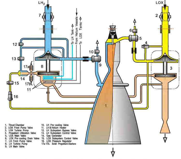
Schematic diagram of stage-3 propulsion engine for "Long March" series
III.
The propulsion system uses liquid hydrogen (LH) as a fuel which is being
mixed with liquid oxygen (LOX) in the upper part of the thrust chamber where
ignition of the explosive mixture takes place. In a subsystem, small
portions of hydrogen and oxygen are being mixed in a gas generator. After
preheating, the now gaseous mixture has a remarkable pressure and can
therefore drive the LH and LOX pumps. The escaping gas composition of the
subsystem can then be released (or even burnt) in a side chamber and thus
add to the thrust of the main chamber.
As to the "solid propellant starters" (items 17a,b) in the above drawing, I
could imagine that these are solid state fuel cells for the "cold burning"
of explosive gaseous mixture in the subsystem, thus generating a certain
amount of electricity for initial operation of the pumps and ignition in the
thrust chamber. Yet, this cannot be verified by additional information.
ARIANE ROCKET PROGRAM
Ariane 1 Launcher
Ariane 1 was a three-stage launcher that had a total height of 47.8 m and a lift-off mass of 210 tons. The first stage had a dry mass of 13.3 tons, a height of 18.4 m and a diameter of 3.8 m. It had four Viking 5 engines (Fig. 2) that developed 2500 kN thrust on lift-off. Burn-time in flight was 146 s. The 148 tons of propel-lant (UDMH and N2O4) were contained in two identical steel tanks protected again internal corrosion by an aluminum layer and connected via a cylindrical skirt. The four turbopump Viking engines were mounted symmetrically on a thrust frame and articulated in pairs on two orthogonal axes to provide for three-axis attitude control. An annular water tank, located inside the propulsion bay, provided for cooling the gas obtained from the engine gas generators that was used to pressurize the propellant tanks and supply the hydraulic motors of the attitude control actuator systems. Four fins with a surface area of 2 m2 provided aerodynamic stability. This first stage was designed to destruct approximately 30 seconds after stage one to two separation.
Figure 2. Viking engine flow diagram. The
Viking engine uses the gas generator cycle, and the gas generator itself
operates at a stoichiometric ratio. The gas produced is cooled by injecting
water to reduce gas temperature to values compatible with the turbopump
turbine, pressurization of the main propellant tanks, and operation of the
power pack for the hydraulic servoactuators. The three pumps (UDMH, N2O4,
and water) are mounted on a single shaft that rotates at 10,000 rpm. (For
Ariane 1, the chamber pressure was limited to 53.5 bars.) The hydropneumatic
regulation system slaves the combustion pressure to a reference pressure
value by adjusting the gas generator feed and, thus, the rotational speed of
the turbopump. The mixture ratio is maintained at a constant level by a
regulator that equalizes propellant pressures before injection into the
combustion chamber. Engine ignition is induced by the pressure in the
propellant tanks. When the valves open, the propellants, which are
hypergolic, are delivered to the combustion chamber and gas generator and
ignite spontaneously. The turbopump speed then builds up to the value set by
the regulating system in 1.3 s.

The second stage had a dry mass of 3.13 tons (excluding the
interstage conical skirt and the jettisonable acceleration rockets), its
height was 11.6 m, and its diameter was 2.6 m. It had a single
Viking 4 engine that developed 740 kN thrust in vacuum for a burn-time of
136 s. The motor was linked to the conical thrust frame via a gimbal with
two degrees of freedom, that provided pitch and yaw control. Auxiliary
nozzles supplied with hot gas from the engine gas generator provided the
roll control function. The two aluminum alloy tanks that had a common
intermediate bulkhead were pressurized with helium gas (3.5 bars) and
contained 34.1 tons of propellant (UDMH and N2O4). The second stage was also
designed to destruct about 30 seconds after stage two to three separation.
During the prelaunch waiting period on the pad, a thermal shroud, ventilated
with cold air, which restricted heat exchange between the propellants and
the environment, protected the second-stage tanks. This shroud was
jettisoned on launcher lift-off.
The third stage weighed 1.164 tons dry, was 9.08 m high, and had a
diameter of 2.6 m. This was the first cryogenic stage produced in
Europe. It was equipped with a type HM7A engine that developed 62 kN thrust
in vacuum for a burn-time of 545 s. This engine was designed by Societe
Europeenne de Propulsion (SEP), based on experience acquired with an earlier
cryogenic engine, the HM 4, which delivered 40 kN thrust, and tested over
the period 1962-1969. The HM 7a engine uses the conventional gas generator
cycle technology, and achieves a specific impulse of 443 s with a mixture
ratio of 4.43 at pump inlet. The combustion chamber is supplied with
propellants pressurized by a turbopump, via a set of injection valves. The
pump turbine is driven by gas supplied by a generator, the latter receiving
a small proportion of propellant tapped off at the pump outlet. The liquid
hydrogen and liquid oxygen tanks that contained a total of8.23 tons of
propellant were made of an aluminum alloy and had a common intermediate
bulkhead (double skin under vacuum). The tanks were covered with external
thermal protection to avoid warming the propellant. Both tanks were
pressurized in flight, using hydrogen gas tapped at the outlet from the
regenerative chamber and helium. The motor was linked to the conical thrust
frame via a gimbal that provided pitch and yaw control. Auxiliary nozzles
ejecting hydrogen gas were used for roll control.
The stages were separated by pyrotechnic cutter devices fitted on
the rear skirts of the second and third stages. The separating
stages were distanced from each other by retrorockets incorporated in the
lower stage and acceleration rockets mounted on the upper stage. Stage 1 to
stage 2 separation was controlled by the onboard computer, on detection of
first-stage thrust decay (propellant exhaustion). Stage 2 to stage 3
separation was controlled by the onboard computer when the second-stage
speed increase reached 1500 m/s.
The vehicle equipment bay (VEB) weighed 316 kg, had a
diameter of 2.6 m, and was of 1.15 m high. Mounted on the third stage, the
VEB contained the electronic equipment of the launcher and also served as a
base for the payload and fairing. In addition to the onboard computer, the
VEB housed all of the electrical equipment required for executing the
launcher mission, namely, the sequencing unit, guidance and navigation
control, and the location, safety, and telemetry systems. Only the power
systems and actuator devices were located elsewhere in the launcher stages.
The two half-fairings were ejected parallel to the main axis of the
launcher under the control of the onboard computer, as soon as the
calculated thermal flux dropped below the specified level. The fairing was
jettisoned by two pyrotechnic systems, a horizontal system at the interface
with the VEB and a vertical system which also served to impart horizontal
velocity to each half-fairing. The fairing was 3 m in diameter and was
compatible with Atlas-Centaur class satellites.
The launch facilities in French Guiana (ELA 1:Ariane launch
site No1) were designed to make use of the earlier investment for the Europa
2 launcher. The stages were erected and assembled directly on the launch pad.
A mobile gantry sheltered the launcher and provided for assembly of the
payload with the launcher and closure of the fairing under clean room
conditions. The gantry withdrawal commenced 6 hours before lift-off. The
main fueling of the third stage with liquid hydrogen and liquid oxygen and
final topping off were performed using a cryogenic arm system carrying a set
of umbilical valve plates. Disconnection and retraction of the arms
commenced at time T — 3 s. Control of the launcher on the pad was fully
automatic from time T — 6 minutes. The launcher was then controlled by two
ground computers, one for the electrical systems and the other for the
propellant and fluid systems. The two computers also crosschecked each other.
The first stage engine was ignited at time T, and the lift-off command
signal was sent at T + 3 s, following satisfactory verification of the
Viking engines. The first flight took place on Christmas eve 1979 (Fig. 3).
When the Ariane program was first initiated in 1973, few
imagined a commercial career for the launcher. Things began to move in 1976
and led to a series of actions relating to launcher performance, production,
and marketing. As regards performance, the idea was to propose Ariane for
launching the Intelsat satellites. The success of such a venture would
represent both an exceptional reference for the program and strong
motivation for the players involved. However, the first task was to augment
performance objectives up to 1600 kg minimum in GTO. Fortunately the prudent
approach adopted for the basic definition of the launcher, combined with the
results of the first flight, demonstrated propulsion performance in excess
of specifications and made it possible to exceed the initial objective and
achieve a figure of 1850 kg.
As far as production was concerned, it was obvious that
there was no hope of selling the launcher if one waited to receive orders
before commencing manufacture. It was on these lines that discussions were
opened at the European Space Agency, and a promotional phase was duly
adopted. Apart from the production of six launchers, the objective of this
phase was to achieve full operational qualification, develop and validate
the dual launch capability, and adapt the launcher comprehensively to meet
user needs by providing for the construction of payload preparation
facilities in French Guiana. Analysis of marketing aspects led to two
actions: initiation of the Ariane 3 program and formation of Arianespace.

Figure 3. Launch L0 1 (24 December 1979).
The decision to proceed directly to flight tests, using three active stages
in the final flight configuration, was made following very lengthy
discussions at the start of the Ariane program. This was in total opposition
to the highly progressive, but also extremely costly approach adopted for
the Europa 2 program. Initial ignition occurred on 15 December 1979,
following a faultless countdown. Unfortunately, the ground computers did not
authorize liftoff, and the engines shut down automatically at time T + 10 s
and aborted the launch. Subsequent analysis showed that an explosion in a
small measurement pipe had damaged the sensors, whose signals were used for
operational diagnosis of the engines. The case of an aborted launch, for
which the probability was infinitely small, had, nevertheless, been taken
into account during the development phase. Procedures for return to flight
configuration had been written and validated by tests conducted in Europe.
This allowed restarting the count on 23 December, following 8 days of round-the-clock
work. Technical problems, combined with adverse meteorological conditions,
prevented a launch on 23 December. On the following day, Ariane made a
practically faultless launch. Only two anomalies were identified, and these
were corrected before the following flight. These concerned minor pollution
of the payload, caused by the second-stage retrorockets and low amplitude
vibrations (POGO effect) at the end of the second-stage flight. The first
Ariane launch thus took place only 6 months after the initial target date
set in 1973.
Ariane 5 Launcher
The Ariane 5 launcher stands approximately 51. 5 m high; the actual figure depends on the upper composite configuration, and the lift-off mass is 740 tons. Lift-off thrust is 11,660 kN. On the ground, the central core vehicle that has an outside diameter of 5.46 m is suspended at the level of the first-stage forward skirt between two solid propellant boosters. This connection, through which the thrust of each booster is introduced in the core stage, is made of alternate elastomer and metallic shims, designed to provide a damping effect on vibrations induced by booster combustion (Fig. 6).
The cryogenic main stage, developed under Aerospatiale as the prime
contractor, is 30.5 m, and its dry mass is 12.2 tons. This stage
contains 158 tons of liquid hydrogen and liquid oxygen. The Vulcain engine (Fig.
7) is mounted on a thrust cone that distributes thrust evenly at the base of
the liquid hydrogen tank. The engine can be oriented along two orthogonal
axes by hydraulic actuators operating on the lost fluid principle. This
fluid is stored in tanks operating in the blow down mode. Connecting struts
between the main stage and the solid propellant boosters provide rigidity
for the rear part. The light alloy propellant tanks have a common bulkhead,
insulated with expanded polyurethane. The hydrogen tank has a volume of 390
m3 and is pressurized at values that vary according to the flight phase (between
2.15 and 2.35 bar), using hydrogen tapped at the outlet from the engine
regenerative circuit. The oxygen tank (120 m3)isin the upper position and is
pressurized with helium gas (3.5 dropping to 2.85 bar), obtained by heating
liquid helium in a heat exchanger located in the oxygen turbine exhaust line.
This helium (1.15 m3) is stored in a super insulated tank mounted on the
thrust frame. The engine control system is supplied with helium gas stored
under pressure in separate tanks. A thrust frame, secured to the upper part
of the oxygen tank, receives the thrust of the solid propellant boosters,
which is then distributed evenly toward the upper composite.

Figure 6. This is a cutaway drawing of Ariane 5. The core is the
Vulcain Engine with a payload of two satellites shown above the fuel tanks.
The two solid strap-on motors are shown on either side of the core.

Figure 7. ARIANE 5 - Vulcain flow diagram. The
Vulcain engine delivers 1140 kN thrust in vacuum and has a specific impulse
of 432 sec. It uses conventional gas generator cycle technology. The
propellants are delivered by two independent turbopumps. The liquid hydrogen
unit operates at 34,000 rpm and comprises a two-stage centrifugal pump,
preceded by an inducer that ensures favorable intake characteristics. This
pump is driven by a 12-MW, two-stage turbine. The pump delivers up to 560
L/s of liquid hydrogen at a pressure of 17 MPa. The single-stage liquid
oxygen turbopump operates at 13,400 rpm and delivers 177 L/s of propellant
at 13 MPa (3.7 MW). The two turbines are driven in parallel by a single
radial injection gas generator, that operates at a combustion pressure of 8
MPa. The generator is supplied with propellant tapped off at the pump outlet.
The combustion chamber pressure is 110 bar. The liquid hydrogen enters the
propulsion chamber via an annular distributor. Most of this flow is routed
through channels integrated in the double-walled structure of the combustion
chamber and throat assembly. The nozzle is cooled by a simple process known
as dump cooling: the remaining hydrogen flow is routed through 460 spirally
welded iconel tubes, whose diameters increase to give a continuous, bell-shaped
surface, then escapes through micronozzles set along the bottom rim of the
main nozzle. Although these gases do not undergo combustion, they are heated
during the trip and contribute to overall thrust. The turbopumps, gas
generator, and combustion chamber ignitions are started by pyrotechnic
cartridges. The mixture ratio (mean value 5.25) is adjusted by a two-way
valve, used to modify this ratio to terminate combustion on quasi-simultaneous
depletion of the two propellants.
Europropulsion (joint subsidiary of SNECMA/SEP and FIAT/BPD) was the prime
contractor for development of the Ariane 5 solid propellant boosters.
Each booster is 31.16 m high, with a diameter of 3.05 m and
a post-combustion mass of 39.3 tons. It contains 238 tons of solid
propellant grain, a composite with an ammonium perchlorate and polybutadiene
base charged with aluminum. The booster casing is made of a high-strength
low-alloy carbon steel and comprises seven cylindrical sections and two
bulkheads. The sections are flowturned to a thickness of 8 mm from forged
preforms and then assembled using a tang and clevis connection. The sections
and bulkheads are assembled to form three segments, each of which is loaded
independently with propellant. Internal thermal insulation, made of rubber-based,
silica or fiber-filled material, protects the structure from hot combustion
gasses. The forward segment is loaded with a 20 tons, star-shaped solid
propellant block in Italy. In view of the mass and size of the boosters, a
dedicated plant has been constructed in French Guyana for fuelling the
central and rear segments (approximately 110 tons of pro-pellant each).
The nozzle, with a flexible bearing made of alternate
elastomer and metallic shims, can be steered up to 6° to control the thrust
vector. The hydraulic actuators are driven by fluid stored within high
pressurized, carbon-fiber vessels operating in blow-down. This fluid is
ejected at the nozzle exit. The nozzle, which is highly integrated with the
motor, represents a prudent extrapolation of the nozzles developed and
qualified for defense applications. The throat in carbon/ carbon material
ensures minimum erosion during flight. The exit cone is composed of a light
alloy housing, with phenolic carbon and silica insulation.
The boosters are jettisoned from the core stage by means of
pyrotechnic cords. Solid fuel thrusters located in the rear part
and in the forward cone are used to distance the boosters from the launcher
in a radial plane.
The booster thrust evolves in flight in order to limit general loads,
with a maximum of 6,700 kN and an average value of 4,900 kN in vacuum. It
must remain within very tight tolerances to limit any thrust differential
between the two boosters at any moment. The maximum combustion pressure is
60 bar, and the specific impulse in vacuum is 270 s.
The vehicle equipment bay is 1.56 m high and constitutes a linkage
structure between the first stage, second stage, and fairing.
Developed under the prime contractorship of DASA, the
second stage is fitted inside the vehicle equipment bay. This is an internal
and relatively compact stage, with a diameter of only 3.94 m and a height of
3.36 m. The dry mass is about 1,250 kg. This second stage carries the
payload adaptor (Fig. 8).
The propulsion system comprises an “Aestus” engine, burning
storable hypergolic propellants (MMH and N204), loaded in helium-pressurized
tanks and consequently requiring no turbopump. This technological solution
was adopted for its reliability, and its simple operation and re-ignition. A
total of 6,550 kg of N204 and 3,200 kg of MMH (maximum load mass) are
contained in two pairs of identical cylindrico-spherical tanks, arranged
axisymmetrically two by two. The lift-off mass is 11 tons.
The engine combustion chamber, extended by a nozzle in
refractory steel, is cooled by an MMH circuit. The mixture ratio is adjusted
to a value of 2.05 by calibration on acceptance testing. The engine can be
oriented through an arc of +4.8° on two axes, using electrical servo
actuators. The Aestus engine develops 29.1 kN thrust and has a specific
impulse of 324 s. The burn-time is about 19 min.
RL-10 Engine

RL-10 is a closed Expander Cycle Engine which does not rely on a gas generator to deliver the hot gas that drives the turbopump turbines of the engine. Instead, the turbines are driven by expanded hydrogen gas that is generated by running the flow of Liquid Hydrogen from the LH2 turbopump through the regenerative cooling system of the upper nozzle segment and the combustion chamber. The gasified Hydrogen then passes to the main turbine of the engine, spinning the LH2 turbopump as well as the LOX turbopump through a gearbox.
Rl-10 includes seven engine valves starting on the fuel side with the Fuel Pump Inlet Shutoff Valve and on the oxidizer side with the Oxidizer Pump Inlet Shutoff Valve. Fuel flow into the combustion chamber can be stopped by the Fuel Shutoff Valve that is located just upstream of the combustion chamber injector.
This valve is used to rapidly cut the fuel feed to the engine for shutdown and its closure also allows the chilldown of the LH2 turbopump through overboard vents without any fuel entering the chamber. Engine LH2 pump chilldown is accomplished by opening Fuel-Cool-Down Valves 1 & 2 that vent coolant overboard during chilldown. These two valves also provide fuel pump bleed during pre-start and pressure relief during shutdown.

Thrust of the engine is controlled by a Thrust Control Valve located in a bridge between the fuel cooling outlet on the engine and the combustion chamber fuel inlet to bypass the turbine and thus regulate turbine power and overall engine thrust. Normally in a closed position, the system is mainly used to control thrust overshoot during engine start and to maintain a constant chamber pressure during steady state operation.
In the oxidizer line downstream of the pump is a Oxidizer Flow Control Valve that is used to regulate the LOX flow to the chamber for the regulation of the mixture ratio that is commanded by the Propellant Utilization Unit of the engine which controls the MR for an optimized propellant consumption. A second OCV is employed to regulate the bleed flow during engine start.

Engine start on the RL-10 is accomplished by using the pressure differential between the fuel feed and the near-vacuum in the chamber that forces fuel through the system after the Fuel Shutoff Valve is opened and FCV-1 is closed. FCV-2 remains in an open position to prevent stalling the LH2 pump of the engine in start-up. In the initial stages of start-up, heat from the ambient metal is sufficient to generate Hydrogen gas to start driving the turbopumps and initiate the combustion process in the chamber, heating up the chamber and nozzle to operational levels. For start, the Oxidizer Control Valve is partially closed to ensure a fuel-rich ignition, limiting chamber pressure in order to maintain a pressure differential in the fuel system until the turbopumps can accelerate.
When the pumps are at flight speed, pneumatic pressure is used to close the Fuel Cooldown Valve and open the Oxidizer Control Valve to achieve the planned LOX pump discharge properties. The opening of the OCV leads to a sharp increase in chamber pressure that can lead to thrust overshoot which is prevented by a temporary opening of the Thrust Control Valve until stable steady-state conditions are reached for engine operation.
In steady state operation, RL-10 consumes 20.6 Kilograms of LOX per second while LH2 flow is approximately 3.5 Kilograms per second.
RS-25 Space Shuttle Main Engine Diagram

Universal Rocket Module as Booster

When used as a strap-on booster, the Universal Rocket Module uses an aerodynamic nose fairing that is attached to the top of the vehicle, covering the top portion of the upper bulkhead of the Liquid Oxygen Tank. The nose cap utilizes light-weight composite materials. The caps are approximately 2.4 meters tall.
The URM boosters interface with the core stage at three points using spar booms that firmly hold the booster URMs in place secured to the core stage. Thrust from the boosters is transferred to the vehicle via the upper spar boom that interfaces with the interstage section of the core stage and the URM-2 upper stage.
When being used as a booster, the URM fires its RD-191 at full throttle throughout the booster stage of the flight with the exception of a throttle down around Maximum Dynamic Pressure. Firing at full thrust, the boosters consume their 132,600-Kilogram propellant load faster than the core that throttles down quickly after liftoff. The boosters burn for 213 seconds before separating from the Core Stage that then throttles up for the rest of its burn – using propellants saved during the boost stage.
Separation of the boosters is accomplished using pyrotechnic bolts that disconnect the spar booms between the boosters and the core stage. Solid-fueled retrorockets are fired to ensure a clean separation without re-contact between the boosters and the core stage.
Universal Rocket Module & RD-191 Engine

| Type | URM-1 (Universal Rocket Module) |
| Length | 25.695m |
| Diameter | 2.90m |
| Fuel | Kerosene (RP-1) |
| Oxidizer | Liquid Oxygen |
| Inert Mass | 9,800kg |
| Propellant Mass | 128,000kg (Partial Propellant Load) |
| Launch Mass | 137,800kg |
| Propellant Tanks | Aluminum Alloy, Intertank Section |
| Tank Pressurization | Helium |
| Propulsion | RD-191 |
| Engine Type | Staged Combustion |
| Thrust – Sea Level | 1,922kN |
| Thrust – Vacuum | 2,085kN |
| Specific Impulse SL | 311.4s |
| Specific Impulse Vac | 337.5s |
| Throttle Range | 27-105% |
| Mixture Ratio | 2.63 |
| Engine Diameter | 2.10m |
| Engine Length | 3.78m |
| Engine Dry Weight | 2,290kg |
| Engine filled Weight | 2,520kg |
| Chamber Pressure | 262.6bar |
| Burn Time | 240s |
| Guidance | Inertial |
| Pitch/Yaw Control | Hydraulic Engine Gimbaling +/-8° |
| Roll Control | 4 Nozzles & Control Surfaces |
| Engine Start | Pyrophoric TEA |
| Restart Capability | No |
| Stage Separation | Cold-Staging |
The Universal Rocket Module is common across the entire Angara family – it is used as Core Stage and can also function as a strap-on booster. Being the smallest of the family, Angara 1.2 uses only one URM acting as first stage. The URM is 25.7 meters long and 2.9 meters in diameter featuring the common structure with the oxidizer tank located above the fuel tank. The URM, when fully fueled, has a launch mass of 141,500 Kilograms with an empty mass of just under ten metric tons.
URM uses Liquid Oxygen as oxidizer and rocket-grade Kerosene fuel, stored in tanks consisting of hemispherical bulkheads and cylindrical sections. Aluminum alloy is used to manufacture the tanks and the URM uses composite materials in its interstage and instrument bay utilizing lessons learned from improvements of the Proton rocket that allow Angara to make use of production techniques creating light-weight components. The LOX feedline is routed on the exterior of the Kerosene tank to reach the engine compartment. The two tanks use individual bulkheads, creating an intertank area which is used to accommodate various instrumentation and control equipment.
Spherical Helium bottles are located inside the Liquid Oxygen tank to be submerged in LOX to improve gas storage efficiency. Helium is used for tank pressurization in flight, being heated up and fed to the tanks to keep them at the proper pressure levels. Helium loading begins once the bottles are submerged in Liquid Oxygen in order to be chilled down to accommodate the Helium.
The Universal Rocket Module is powered by a single RD-191 engine which is a one-chamber version of the RD-171 engine used on the Zenit rocket that is based on the RD-170 designed for the Energia rocket. The NPO Energomash RD-171 had already been converted to the two-chamber RD-180 currently used on the Atlas V launch vehicle. In the process of designing the RD-180, a study of creating a one-chamber version was conducted and the development of the engine was started in the late 1990s.
The first test firing was conducted in 2001 and the total testing program included 120 firings with a cumulative duration of 26,892 seconds. RD-191 completed its test program in 2011 and was certified in 2013 after another 18 firing tests.
Overall, RD-191 is 3.78 meters tall and has a nozzle diameter of 2.1 meters. The engine has an inert mass of 2,290 Kilograms. RD-191 is attached to the launcher via a gimbal truss and a spacer to the shell of the lower fuel tank.
RD-191 delivers a sea level thrust of 1,922 Kilonewtons (196,000kgf) with a specific impulse of 311 seconds. Thrust rises to 2,085kN (212,600kgf) in vacuum conditions with a vacuum impulse of 337.5 seconds. Through its design, RD-191 is capable of extremely deep throttling down to 27% of nominal performance. In flight, RD-191 will normally be throttled down no lower than 30%. The engine can also operate at 105% of rated performance for short periods of time which is utilized in contingency scenarios.


RD-191 uses a staged combustion scheme – burning all of the oxygen with little fuel inside a Gas Generator to produce a hot high-pressure gas to drive the turbine that powers the fuel and oxidizer turbopumps. The engine features boost pumps at the fuel and oxidizer inlets that operate at a lower speed than the main pumps and create an engine inlet pressure sufficient for the operation of the turbopumps. The fuel boost pump is powered by a turbine driven by the fuel tapoff from one main pump (fuel returns to the inlet) and the oxidizer boost pump turbine is driven by a fraction of the hot gas from the gas generator that then enters the LOX flow and condenses.
All of the oxygen is then directed to the LOX impeller turbopump before reaching the Gas Generator. The Kerosene flow is directed into two portions using a two-stage turbopump. The Kerosene flow from the second pump stage (about 20% of total flow) is directed into the Gas Generator were it is burned in an excess of oxidizer, creating a high-pressure, oxygen-rich gas that drives the turbine. The RD-191’s LOX turbopump and fuel pumps are mounted on a single shaft. The turbine itself is a axial turbine using relatively thick blades and large clearance between the gas inlet and the blades to reduce the risk of damage. Nickel-alloys are used to endure the hot temperatures of the gas from the generator and the turbine uses cold oxygen for additional cooling.
The Kerosene from the first stage pump is directed to the combustion chamber and nozzle where it passes through heat exchangers as part of the regenerative cooling scheme of the engine. The engine uses three cooling paths, one entering at the combustion chamber, one entering at the nozzle throat and the third one entering at the nozzle exit. After passing through the heat exchangers, the fuel is pumped into the combustion chamber where it is burned by the oxygen-rich gas coming from the gas generator. The mixture ratio is adjusted by a mixing valve located behind the first stage turbopump and the Gas Generator Temperature and engine thrust are regulated via flow valves ahead of the Gas Generator. RD-191 has a nominal mixture ratio of 2.63.
Regenerative Cooling Flow

RD-191’s chamber consists of the mixing head, the combustion chamber and the nozzle. The injector uses small nozzles through which the components are introduced into the combustion chamber, forming a circular inner zone separated from an outer ring by protruding nozzles.
The outer ring is divided into six compartments using protruding nozzles through which propellants enter the chamber. Fuel and oxidizer-rich gas alternates between the seven compartments. This design allows a stable combustion and avoids combustion instability or the creation of hot spots. RD-191 operates at a nominal chamber pressure of 262.6 bar.
.
RD-191 Mixing Head & Chamber Design


RD-191 uses a chemical ignition system based on Triethylaluminium (TEA) – a pyrophoric substance that immediately ignites upon exposure to oxygen. The TEA is stored in two closed ampoules – one in the fuel line directly ahead of the Gas Generator and one in the main fuel inlet to the combustion chamber. These ampoules use membranes to prevent the TEA from coming into contact with air.
For engine start, a dedicated spherical Kerosene, tank that is connected to both fuel lines via plumbing and associated valves, is filled with fuel and pressurized using high-pressure gas. Once the valves to the fuel lines and ampoules are opened, the high-pressure fuel drives pistons that are part of the ampoules to create a pressure inside the cavity that causes the TEA to be released into the Gas Generator and combustion chamber that have been filled with oxygen by that point after LOX valves are opened and the tank pressure causes oxygen to enter the engine.
Coming into contact with oxygen, the TEA ignites and starts the combustion process inside the Gas Generator and the main chamber. The combustion is sustained by Kerosene entering the GG and combustion chamber right after the TEA. Once the Gas Generator is running, the turbine spins up to speed and the turbo and boost pumps begin pumping propellants to the Gas Generator and Combustion Chamber, thus sustaining the combustion process.
Using this ignition technique means that RD-191 can only be ignited once and requires extensive refurbishment after each ignition (replacing the TEA membranes and re-filling the ampoules).

For tank pressurization, Helium flows from the Helium spheres inside the LOX tank down to the engine compartment where it is heated up inside a heat exchanger connected to the hot gas flow from the Gas Generator to the LOX Boost Pump. The pressurized heated Helium is then pressed into the LOX and Kerosene tanks to keep them at the proper pressure via a series of valves that control the pressurization. The initial pre-flight pressurization is accomplished using pressurized gas supplied by ground support equipment.
RD-191 uses a cardan suspension which allows it to gimbal +/-8 degrees using a hydraulic system driven by the gas generator exhaust. Engine gimbaling can only achieve control on the pitch and yaw axis requiring an additional system for roll control.
For that, hot has from the RD-191 gas generator is released through four nozzles onto two aerodynamic control surfaces that deflect the stream of hot gas and introduce a roll component depending on their position. The control surfaces on the outside of the tail section are moved using hydraulic pressure.
Being a modern engine, RD-191 includes various pressure, flow and temperature sensors that provide detailed performance data to the engine controller and flight computers. This allows a detailed monitoring of performance and extensive post flight analysis which can be useful in case of any anomalies. Also, telemetry is used in real time by the vehicle’s control system to adjust engine parameters like mixture ratio to optimize the performance of the launch vehicle via optimal propellant utilization. Additionally, engine telemetry is used to trigger launch vehicle abort modes.
The Universal Rocket Module houses control system devices, telemetry measurement systems, power supply units and batteries inside the intertank section. The URM control system is common across the entire Angara family and uses heritage components from the Proton-M and Briz-M vehicles. Functions of the URM control system include control of the engine, monitoring of propellant consumption, monitoring of vehicle health, engine gimbal control, control of aerodynamic surfaces and telemetry transmission to the ground.
The control equipment is self-contained and inertial using a modular structure that permits the addition of components at minimal difficulty. URM houses its own inertial guidance unit and also receives commands from the digital flight control system facilitated on the second stage.
Unlike the Soyuz, Angara uses a cold-separation sequence between the URM-1 and the second stage instead of the hot-staging of Soyuz in which the RD-0124 engine ignites before separation to be able to push the spent Core Stage away.
For staging on the Angara launcher, the RD-191 engine is shut down followed by a short delay before the pyrotechnic stage separation sequence is initiated, cutting the structural connection between URM-1 and the second stage. Next, four solid-fueled retrorockets are ignited on URM-1 located in the interstage area. These rockets move the Core Stage away from the second stage, clearing the way for engine ignition after a pre-programmed interval.
Second Stage – URM-2 & RD-0124A Engine

| Type | URM-2 – Modified Block I |
| Length | 6.87m |
| Diameter | 3.6m |
| Fuel | Kerosene (RP-1) |
| Oxidizer | Liquid Oxygen |
| Inert Mass | 4,000kg |
| Max LOX Mass | 25,100kg |
| Max Kerosene Mass | 10,700kg |
| Max Launch Mass | 39,800kg |
| Propellant Tanks | Aluminum Alloy with Intertank |
| Tank Pressurization | Helium |
| Propulsion | RD-0124A |
| Engine Type | Staged Combustion, Closed Cycle |
| Thrust – Vacuum | 294.3kN |
| Specific Impulse Vac | 359s |
| Engine Diameter | 2.400m |
| Engine Length | 1.575m |
| Engine Mass | 548kg |
| Thrust-to-Weight | 54.7 |
| Burn Time | 424s |
| Specific Impulse | 359s (Vac) |
| Chamber Pressure | 157bar |
| Restart Capability | No |
| Ox to Fuel Ratio | 2.34 |
| Turbine Temp. | 973K |
| LOX Flow Rate | 56.7kg/s |
| RP-1 Flow Rate | 23.9kg/s |
| Turbine Inlet | 319bar |
| Turbine Outlet | 185bar |
| Attitude Control | Chamber Gimbaling +/-3.5° |
| Shutdown | Commanded Shutdown |
The second stage of the Angara launch vehicle family is a modified Block I which, in its original configuration, is used on the Soyuz 2 rocket.
For Angara’s URM-2, the original diameter of the Block I is widened from 2.66 meters to 3.6 meters in order to significantly increase the propellant load of the stage by a factor of 1.4. In turn, the stage also grew about 13 centimeters in length due to the use of different bulkhead shapes on the propellant tanks.
Measuring 3.6 meters in diameter, the URM-2 second stage is wider than the URM-1 first stage of the Angara 1.2 launch vehicle. The mass of this fully fueled second stage would be too much to handle for the RD-191 engine of the first stage which would not reach a sufficient thrust to weight ratio at liftoff.
Originally, it was planned to launch Angara 1.2 with a reduced fuel load of 25,700kg on the second stage, but in 2009 the design was changed – introducing a different modification of the Block I only for the light-lift Angara 1.2 which would keep the basic Block I dimensions, but use the RD-0124A engine and Angara control systems.
For the sub-orbital test launch, Angara 1.2PP will fly in its original design with the larger URM-2 stage to certify it for later flights on the Angara A5 rocket.
The Universal Rocket Module-2 is 6.87 meters long and 3.6 meters in diameter with an empty mass of approximately 4,000 Kilograms. It is comprised of two tank compartments to facilitate the fuel & oxidizer tanks, an intertank section and a propulsion section in the aft of the stage where the RD-0124 engine resides. Overall, the stage can be filled with up to 35,800 Kilograms of propellants for a total launch mass of close to 40 metric tons.
URM-2 uses aluminum alloy tanks – the lower tank facilitates 25,100 Kilograms of Liquid Oxygen using two hemispherical bulkheads with a cylindrical section in between, the Kerosene tank above the LOX tank holds 10,700 Kilograms of fuel consisting of two hemispherical bulkheads with a very small cylindrical section. The Kerosene feedline runs from the fuel tank down the outside of the LOX tank to reach the engine compartment.
Using separate bulkheads, the tanks have a small intertank section between them that is used to house the flight computers and various control equipment. The conventional Block I uses a three-segment aft structure to protect the upper engine compartment portion and a part of the thrust structure and LOX tank during atmospheric flight. URM-2 uses an interstage adapter that narrows in diameter in order to fit onto the 2.9-meter first stage. During stage separation, the entire interstage separates to expose the engine compartment of URM-2 making any aft cover jettison obsolete.

The URM-2 stage is powered by an RD-0124A engine which is essentially an RD-0124 from the Soyuz with two modifications – it uses a different structural design with a reduced number of components and lighter materials, reducing the overall weight of the engine by 24 Kilograms and improving its thrust to weight ratio. The second difference is the certification of the engine for a longer burn time than that of the Soyuz. This change comes into play because Angara uses larger URM-2/Block I stage with more propellants requiring the engine to burn up to 424 seconds.

The RD-0124A is a four-chamber engine with a single Gas Generator and turbopump assembly supplying all combustion chambers. This engine is derived from the RD-0110, but is a closed-cycle gas-generator type engine. Overall, RD-0124A is 2.4 meters in diameter and 1.58 meters tall with an empty mass of 548 Kilograms. The engine delivers a thrust of 294.3 Kilonewtons (30,400kgf) and has a specific impulse of 359 seconds – a major improvement over the RD-0110 due to the use of a closed cycle and the higher chamber pressure of that design.
The RD-0124A uses a typical staged combustion cycle of Russian engines with an Oxygen-rich gas generator in which the entire LOX flow is combusted with a small portion of the fuel flow to create a hot high-pressure gas to drive the turbine of the engine which powers the turbopumps. The rest of the Kerosene is used for cooling of the chambers before being injected into the combustion chambers and burned with the oxygen-rich gas.

Propellants entering the engine are pumped to the main turbopumps by separate boost pumps in the Kerosene and LOX lines needed to reach the proper inlet pressure of the main pumps. The turbo-axial boost pumps are similar in design – each unit includes one rotating part that consists of axial pump wheels and a hydraulic turbine, brazed or welded onto the pump wheel external diameter. The boost pump of the fuel inlet is driven by the high-pressure tapoff from the second stage Kerosene turbopump that re-enters the propellant inflow after passing through the turbine. On the LOX side, the boost pump turbine uses a similar scheme – it is powered by a fraction of LOX from the turbopump that also re-enters the feedline.
RD-0124A uses a single shaft to which the LOX turbopump and a two-stage Kerosene turbopump are mounted. The shaft is driven by a turbine powered by the high-pressure gas produced by the Gas Generator.
KVSK Upper Stage

| Type | KVSK |
| Length | 8.3m |
| Diameter | 3.6m |
| Fuel | Liquid Hydrogen |
| Oxidizer | Liquid Oxygen |
| Inert Mass | 2,630kg |
| Propellant Mass | 10,760kg |
| Launch Mass | 13,840kg |
| Propellant Tanks | Aluminum Alloy |
| Tank Pressurization | Helium |
| Propulsion | RD-0146D |
| Engine Type | Expander Cycle |
| Thrust – Vacuum | 68.6kN |
| Specific Impulse Vac | 463s |
| Engine Diameter | 0.96m |
| Engine Length | 3.558m |
| Nozzle Length | 1,95m |
| Engine Mass | 242kg |
| Burn Time | 1,350s |
| Chamber Pressure | 60bar |
| Restart Capability | Up to 5 |
| Settling Thrusters | 8 x 11D428A |
| Fuel | Unsymmetrical Dimethylhydrazine |
| Oxidizer | Nitrogen Tetroxide |
| Thrust | 130N |
| Specific Impulse | 290s |
| Thruster Length | 274mm |
| Thruster Diameter | 93mm |
| Thruster Mass | 1.5kg |
| Burn Time | 0.03s (Impulse) – 2,000s |
| Cycle Life | 40,000 |
| Reaction Control | 8x S5.142A |
| Fuel | Unsymmetrical Dimethylhydrazine |
| Oxidizer | Nitrogen Tetroxide |
| Thrust | 25N |
| Attitude Control | Engine Gimbaling, RCS |
| Flight Duration | Up to 9 Hours |
The KVSK upper stage is the smallest in a series of cryogenic upper stages developed by Khrunichev for the Angara launcher family. The bigger stages, KVRB for Angara A5, and KVTK & KVTK-A7 for Angara A7, carry more propellant and are too heavy for the A3 vehicle. Across the family of cryogenic upper stages, a lot of commonality exists extending the principle of the Angara family – using common components or scaled-up parts to create a simplified assembly and integration process and to cut costs.
KVSK is a single-stage booster consisting of a propellant compartment, an upper equipment compartment and a lower engine compartment. The stage features aerodynamic covers since it is not protected by the payload fairing like the Briz-M. The engine compartment is not protected and needs to be enclosed in a separable interstage section that builds the interface to the second stage, also including electrical and data interfaces.
KVSK is approximately 8.3 meters long and 3.6 meters in diameter with a launch mass of 13,840 Kilograms. It uses cryogenic propellants – liquid Oxygen and liquid Hydrogen for its main propulsion system centered around the RD-0146D engine. Hypergolic propellants are used for the propellant settling thrusters and the attitude control system. Helium is used for tank pressurization stored in spherical high-pressure tanks.
The tanks of the KVSK upper stage are made of aluminum alloy using spherical bulkheads with a cylindrical section between the bulkheads. The tanks use insulation materials (isolane and screen thermal vacuum insulation) and the propellant lines are covered with insulation as well. This is required to prevent an excessive boil-off inside the tanks which is a problem during extended flight profiles. KVSK uses separable connectors for the LOX/LH2 and Helium fill & drain systems that interface with ground support equipment on the launch pad and separate a liftoff. Ground purge flow is directed into the engine compartment and the payload fairing as part of KVSK’s fire prevention system. These interfaces also separate at launch. With the second stage, KVSK communicates using umbilical connectors that are separated at staging and communication with the spacecraft is accomplished through interfaces on the payload adapter.

The RD-0146D engine is based on the original RD-0146 built by the KBKhA design bureau in cooperation with Pratt & Whitney Rocketdyne to design a Russian-equivalent to the RL-10 engine that is used to power the Centaur Upper Stage (Atlas) and the Delta Cryogenic Second Stage (Delta IV). RD-0146 is the first Russian engine not using a gas generator and the first to feature a deployable nozzle extension.
Development of the RD-0146 engine started in 1997 at KBKhA and was partially financed by Pratt & Whitney Rocketdyne, giving the company the international marketing right of the engine. This marked the first step toward Russia’s return to fully cryogenic rocket fuel since the Energia rocket demonstrated the difficulty to control the LOX/LH2 combination in the 1980s. It also is KBKhA’s first engine with separate turbopumps, stepping away from the single-shaft design.
The design of the engine was finished in 2001 and the first components had already been produced by then including ball valves with minimal leakage for Hydrogen. First, engine components were tested individually, such as the igniter. Late in 2001, the first RD-0146 was test fired to start its test program that was completed in 2007. RD-0146 is an expander cycle engine delivering 98.1 Kilonewtons of thrust with a nozzle optimized for operation in vacuum to create a specific impulse of 463 seconds.
With the basic RD-0146 design and development complete, efforts to extend the engine’s capabilities were started to create the RD-0146D with deployable nozzle extension and multiple ignition capability, and the RD-0146DM that uses Liquid Natural Gas instead of liquid hydrogen. RD-0146D has a lower thrust than the original version, but a higher vacuum impulse due to the use of the extended nozzle – it also supports long burns of more than 1,300 seconds. The RD-0146DM variant has a lower thrust and impulse due to the different propellant combination and has not yet been certified for long burns. The D and DM versions began development in 2007 & 2008 – the first test firings began in 2012. The RD-0146D completed vacuum testing, multiple ignition tests and tune-up testing in 2013 to be certified for use in 2015.
RD-0146D stands about 3.56 meters tall with its nozzle extension deployed, creating a nozzle diameter of 0.96 meters and a nozzle length of 1.95 meters. The engine weighs about 242 Kilograms and delivers a vacuum thrust of 68.6 Kilonewtons (7,000kgf) at a vacuum impulse of 470 seconds. The engine uses regenerative cooling on its chamber and fixed nozzle segment while the deployable nozzle is cooled radiatively. The carbon-carbon nozzle extension uses an electromechanical deployment mechanism.

RD-0146D uses an expander cycle that is very different to the staged combustion cycle of gas generator engines. In its principle, the engine expands the hydrogen fuel by running it through the engine heat exchangers to cool the chamber before entering the combustion chamber and being burned with the oxidizer.
The engine uses ball valves in the LOX and LH2 feedlines as engine inlet valves before the propellants run through boost pumps with separate units for the fuel and oxidizer. These boost pumps allow the propellants to be supplied at low pressure (5.1 bar for LOX & 5.7 bar for LH2) and increase the flow and pressure to sufficient levels for the main turbopumps.
The LOX boost pump is operated by a small stream of high-pressure LOX that is taken from the turbopump output, driving the boost pump turbine and being introduced into the LOX flow downstream of the boost pump to enter the cycle again. On the LH2 side, the boost pump turbine is spun by a high-pressure hydrogen stream that is taken from the expanded gas after passing through the turbopump and engine heat exchanger.
After passing the boost pumps, the liquid Oxygen reaches its impeller turbopump that increases the pressure to approximately 130 bar. The LOX turbopump is driven by a turbine that is powered by the hot hydrogen gas from the LH2 turbopump heated & expanded in the heat exchangers. Some of the turbopump output is routed to the LOX boost pump while the rest is directed to the combustion chamber via a regulator for throttle control and a main oxidizer valve. The regulator controls the mixture ratio that is commanded by the engine controller and ensures fuel-rich conditions for start-up and shutdown to maintain chamber integrity. RD-0146 operates at a nominal mixture ratio of 5.9.

Image: NIC-RKP


Each settling thruster delivers 392 Newtons of thrust being 46.9 centimeters long and 19.2 centimeters in diameter with a mass of about 3 Kilograms. 11D458M operates at a mixture ratio of 1.85 and a propellant inlet pressure of 14.7 bar. It can be fired in pulse mode or make long steady-state burns and is certified for firings of up to 1,000 seconds and 10,000 duty cycles. For propellant settling, all four thrusters are activated 15 seconds before the main engine start to provide a forward acceleration for propellant settling inside the large tanks.

The attitude control thrusters used on Briz-M are known as 17D58E providing a nominal thrust of 13.3 Newtons. Each unit is 14 centimeters long and weighs 550 grams. The thruster also operates at a mixture ratio of 1.85 and a nominal inlet pressure of 14.7 bar, but it can tolerate a large pressure range from 7.8 to 34.3 bar. For attitude control, the thrusters are used in pulse mode with a minimum on-time of 0.03 seconds, but 17D58E is also certified for burns in steady-state mode up to 10,000 seconds. The engine is certified for 450,000 duty cycles.
Briz-M is outfitted with an inertial guidance platform, a digital flight computer and batteries that allow the stage to operate for up to 24 hours.

THE ROCKET IN WARFARE
It is sad to reflect that the very inventions which make for the greatest
progress and advancement in peace are equally effective for destruction when
applied to war. The rocket is no exception to this rule.
Marshal Foch is said to have prophesied that in the next war "the whole nation will find itself on the firing line !" It is possible that this remark was grounded on the exploits of Big Bertha in the last war, since the problem of modern warfare has now resolved itself into that of destruction at the greatest distance. And as a means for an attack on a distant foe the rocket stands out as having the most far-reaching potentiality.
For the rocket carries its own fuel, and its motion continues until that fuel is exhausted and its momentum is lost.
And if to the rocket motor there is attached a nose filled with high explosive, gas, disease germs, or anything deadly that modern science can create, we get a self-propelling shell whose trajectory vastly exceeds the wildest dreams of the ballistician.
Figure 6 shows a cross-section of a type of rocket adapted for warfare, upon which experiments are being made. The larger portion of its bulk is taken up with fuel, consisting of liquid oxygen and gasoline. This mixture gives a very high pressure, and, consequently, high velocity of propulsion. Fins are provided to keep the rocket on its course, but some form of gyroscopic control could no doubt also be incorporated.
Such a rocket would not only propel shells to distances utterly impossible by any form of artillery, but

Fig.6. Rocket Shell
Courtesy : "Science and Mechanics"
they could be shot with such rapidity and in such vast numbers as to be
utterly devastating in effect.
Hitherto long range artillery has been used principally against opposing armies at distances of 5 to 25 miles.
The rocket shell, catapulted in the first instance for launching, would rise, gaining headway at each second, and descend at any distance from 500 miles onwards!
As a consequence, London would be in range from both the German and French capitals, Paris from the German border, and Berlin from the Rhine, whilst Switzerland might find herself arched with a mutual bombardment between France and Italy!
The assailants would fire upon known objectives by map, just as modern long range artillery is directed upon invisible targets.
Batteries shooting rocket shells into the heart of an enemy country could be built by the thousand and fired with the rapidity of small calibre artillery. For rocket shells of this kind would be gun and shell in one, and wTould not require any heavy ordnance to shoot them.
Originally it was intended to control and direct these rocket shells by gyroscopic means, so that they should carry themselves unerringly to their objective, but in view of the enormous strides made in wireless the latest designs embody wireless control. Ultra short radio weaves would be employed to control and operate elevating and directional fins forming part of the rocket. The principal difficulty of ascertaining the position of the rocket once it had vanished from view has now been solved by fitting each rocket with a small transmitting apparatus, the constant waves from which at a predetermined frequency can be received by radiogoniometric stations installed in the vicinity of the firing point. By triangulation or other methods these stations would be able second by second to determine the exact position in space of the rockets whilst in flight, and by the aid of their transmitters so to control and direct them as to cause them to fall at any desired locality in the enemy's country.
As is already known this principle of radio control has already been tried with battleships, submarines, and aeroplanes, and it is equally suitable for rocket control.
Another equally appalling factor in the "next wrar" would be the adaptation of rocket propulsion as an auxiliary means of propulsion to a bombing aeroplane.
Rising to their normal "ceiling," such planes, known as rocket stratoplanes, wrould, by the aid of the rockets with which they would be fitted, then "shoot" themselves to a height of 30 miles or more. At this great height, where the air resistance is almost non-existent, speeds of 3000 miles per hour could be attained, and they would be not only immune from attack by opposing planes not using auxiliary rocket propulsion, but beyond the range of audibility and visibility from land observers.
Flashing thus invisibly over the enemy's country at inconceivable speed, they would at the critical moment switch off their motors and swoop suddenly and silently down from the skies upon an unsuspecting city, loose their loads of deadly projectiles, and escape just as swiftly as they came.
Cruisers and other battleships could be also quickly and readily converted into "rocket ships " by fitting trough-like catapults on the backs of the existing guns. Against an invading fleet so armed with long range rocket shells, the heaviest of coast defence guns and naval guns would be as useless as clubs and spears.
The extension of battle areas, both naval and military, would be also as revolutionary as that which followed the introduction of the modern rifle and aeroplane. Just as the much vaunted splendid "insularity" of England now no longer exists, and its frontier is the Rhine, so in the course of a very few years' development in rocket stratoplanes would the "insularity" of the United States be a thing of the past, and her frontier be Japan.
There is no possible doubt that militarists all over the world, with the possible exception of England, are fully alive to the tremendous possibilities of the rocket in modern warfare, and in the next war it will inevitably follow that rocket propulsion will be developed to the fullest extent of its destructive powers just as happened in the Great War with the aeroplane.
In this connection it may be mentioned that Professor Hermann Oberth, the world's greatest authority on the rocket, recently stated before a meeting of scientists in Vienna his belief that the War Offices of every nation of importance were already hard at work developing the rocket for military purposes.
In Germany, for example, German scientists are busily engaged in seeking a means of destroying cities hundreds of miles away by means of stratospheric rockets.
Nominally, the experiments have been made under the pretext of reaching Mars, or the moon, or for a rocket for rapid postal services. Nevertheless, all progress made in this direction has its specific aj)plication as a new weapon of war. For years past experiments under the direction of the Reichswehr Ministry have been made with stratospheric rockets at Meppen, where the first tests with "Big Bertha" were carried out, at Stolp on the Baltic coast, at Britz near Berlin, and at Munich.
It is almost beyond belief that in England to-day nothing is officially known about rockets. At least that is the inference to be gathered from a statement made by the Air Ministry only a few months ago, when in reply to a request to investigate and experiment with rocket propulsion the answer given wTas that "they saw no reason to regard the rocket motor as a serious competitor to the tractor screw!" Competitor, mark you! What earthly competitive chance, as a means of propulsion, has the tractor screw against a rocket in a Vacuum or in a highly-rarefied atmosphere ?
How many people in England to-day realize that far from enjoying a splendid insularity, the gap in the nation's defences is as wide as the heavens themselves ? Who with any gift of vision can fail to be filled with apprehension when they gaze up at the sky, dreading the day when it will be filled with aerial messengers of death with their resultant wholesale massacre of innocent women and children and non-combatants ?
These facts are unpleasant to face — especially for those who hope to see the rocket harnessed to peaceful vehicles that will annihilate distance and possibly achieve the exploration of interstellar space.
Whether mankind of the future will bitterly regret that the rocket has ever been invented remains to be seen. To the author it seems to be one of the creations of the human mind which will serve as a test of man's right to inherit the earth. For good or evil, its powers, like the principle upon which reaction propulsion is based, are "equal and opposite."
Twenty years from to-day we may be shooting across oceans and national borders rockets that hold passengers and articles of commerce, or deadly missiles containing poison gas, microbes, and other means for destroying human lives. Which it will be depends not upon rocket experimenters, nor upon militarists, but upon the people of the world who have to pay, fight, and suffer for all wars.
We will now leave the lugubrious subject of the use of rockets in warfare and, by way of relaxation, indulge in a "flight of imagination "• — to wit, an account of a journey by space ship from Berlin to New York.
Rocket Propulsion, Changing Mass, and Momentum

Free-body diagram of rocket propulsion
(a) This rocket has a mass m and an upward velocity v. The net external force on the system is −mg, if air resistance is neglected. (b) A time Δt later the system has two main parts, the ejected gas and the remainder of the rocket. The reaction force on the rocket is what overcomes the gravitational force and accelerates it upward.
Mechanism of liquid rocket engines

fig3: Open Cycle.
1-Pump of the oxidizer; 2-Pump of the fuel; 3-Turbine; 4-Combustion
chamber; 5-Gas turbine; 6-Fuel overeating; 7-Oxygen overeating; 8-Drainage;
9-Fuel enter; 10-Oxygen enter; 11-Derivation to the tanks; 12-Air embarked
from balloons; 13-Fuel taking away for the pumps mechanism of the combustion
chamber; 14-Drainage of the fuel; 15-Drainage of the oxygen; 16-Drainage of
the turbopump; 17-to the manometer; 18-Combustion chamber; 19-To the melange
regulator; 20-Purge of the fuel duct; 21-To the manometer; 22-Outside air
intake
The main example of the GRD opened cycle are the RD-107 and RD-108 wich use as fuels liquid oxygen and some petroleum, they are installed on the rockets Sputnik, Luna, Vostok, Voskhod, Molniya, Soyouz, as well as engines using some acid nitrogen for the rockets Cosmos, Tcyklon, and the others strategic launchers. Engines with opened cycle have a pressure of 50-80 atm in the combustion chamber. The supplementary increase of the pressure is ineffective because of the losses of growth of the specific impulse caused by a not total use of the chemical energy of fuels.
In engines with closed cycles ( fig.4 ) components burn completely in the combustion chamber. One of them, for example the oxidizer is sent to the gas turbine by the pump, there it is melted with a small quantity of fuel, the process of combustion is not total to insure an acceptable temperature of functioning for the turbine. Later, these gases go to the main combustion chamber where they are added with the rest of the fuel. In this type of engines all the chemical energy of the fuel is used and allows to increase the pressure in its maximum. Today the level of the pressure is 150-270 atm.

fig4: Closed cycle.
Caption:
1-Pump of the oxidizer; 2-Pump of the fuel; 3-Turbine; 4-Chamber of
combustion; 5-Gas turbine; 6-Fuel; 7-Oxygen
The idea of an engine with closed cycle was realized for the first time in 1950 in the IRS (at the moment ФГУП " The Scientific center M.V. Keldysha "), about the engines of great thrusts (150 t at sea level) with a high pressure in the combustion chamber (150 atm) they were realized in the middle of the 60s in ОКБ-456 (at the moment НПО "Энергомаш"). The fuel used in this engine, RD-253, intended for the first Proton rocket was nitrogen tetroxide (N2O4) and unsymmetrical dimethylhydrazine (UDMH). On the Proton rocket the first floor included 6 RD-253 engines, which have already made 300 flights, but the engine is still unequalled today in its class for its energetic characteristics.
The use of the closed cycle and the high pressures to increase the specific impulse became the main direction for the elaboration of the Russian GRD engines for spatial and strategic launchers. So, on the P-36M Satan rocket is installed the RD-264 engine with a chamber's pressure of 210 atm, but on Zenit and Energia rockets RD-171 and RD-170 engines have a pressure in the combustion chamber of 250 atm.
The advantage of this kind of engines is that they are ecologically sure, have a high level on functioning, have a good flexibility of use and consume cheap fuel, such as oxygen and petroleum.

fig5: scheme of the universal combustion chamber.
Caption:
1-Head of the nozzle; 2-Nozzle; 3-Combustion chamber; 4-Tailpipe
The universal combustion chamber of the RD-170 engine of 200 t of thrust is shown on the drawing 5. In the cylindric combustion chamber, of 380 mm diameter, burn 0.6 t of fuel per second in a pressure of 250 atm. Studies were led to exclude in a sure way the instabilities of combustion at high frequency in this chamber. Indeed the initial zone of admittance and combustion where vibrations are created generally in high frequency is divided into 7 identical volumes thanks to anti-vibratory partitions. Nozzles are placed such a way that their oscillation frequency is far from the echo frequency of the combustion chamber. The anti-vibratory systems implementation in the combustion chamber of the RD-120 engines of the Zenit rocket as well as the modernization of the RD-107 and RD-108 engines of the Soyouz rocket confirm the high safety and the efficiency of the found solutions, which will certainly be reused for the future RDG.
The cooling system also benefited of all the experiment of the Soviet engineers. In particular the internal cooling is done by 3 zones of spray. About 2 % of the fuel is injected into it by droplets to protect the buzzards of the extreme temperatures ( 50MW / min ). Such a chamber demonstrated its high working capacity on RD-170 and RD-171 engines in a wide range of parameters (from 30 to 105 % of the pressure of the fuel) during 25 tests before the production.
In the creation of the RD-170 engine, the most powerful, many problems appeared. Pumps responsible for the supply of chambers in fuels were subjected to strong constraints, pump in one stage for the oxidizer and the pump in two stages for the fuel. The pump for the oxidizer work at 14 000 trs / min under a pressure of 600 atm, the pump of fuel of the first level was at 500 atm and the second stage one at 800 atm.
To ensure the functioning of pumps the gas turbine had to develop a power of 190 MW. Which is twice as powerful as the driving group of the atomic icebreaker "Arctic".
To increase the resistance of the oxidizer ducts on the oxidation and on the heat (for the warm ducts) a nickel alloy was applied.
fig6: Engine RD-180.
Caption:
1-Frame; 2-Gases's duct; 3-Turbine's outflow collector; 4-Turbine; 5-Heat
exchanger; 6-Oxidizer pump; 7-Actuators of the oxidizer's turbopump; 8-Fuel
pump of the first level; 9-Fuel pump of the second level; 10,11-Second and
first combustion chambers; 12-Outlet; 13-Starter; 14-Actuator of the rudder;
15-Flexible elements; 16-Actuator of the fuel's turbopump; 17-Crosspiece;
18-Separation valve
Russia's newest rocket engine will power an American space launcher, the two sides agreed this month. In January 2015, the Russian rocket industry struck a deal with a US company to supply a modified version of the RD-191 engine for the US Antares rocket. The RD-191 engine was originally developed for Russia's new-generation Angara family of rockets and was already modified under name RD-151 to propel the South-Korean KSLV-1 launcher. The latest US-Russian agreement puts another upgrade of the engine, designated RD-181, on the first stage of the Antares rocket developed by the Orbital Sciences Corporation, OSC.


Rocket Science - The basic of a rocket engine..
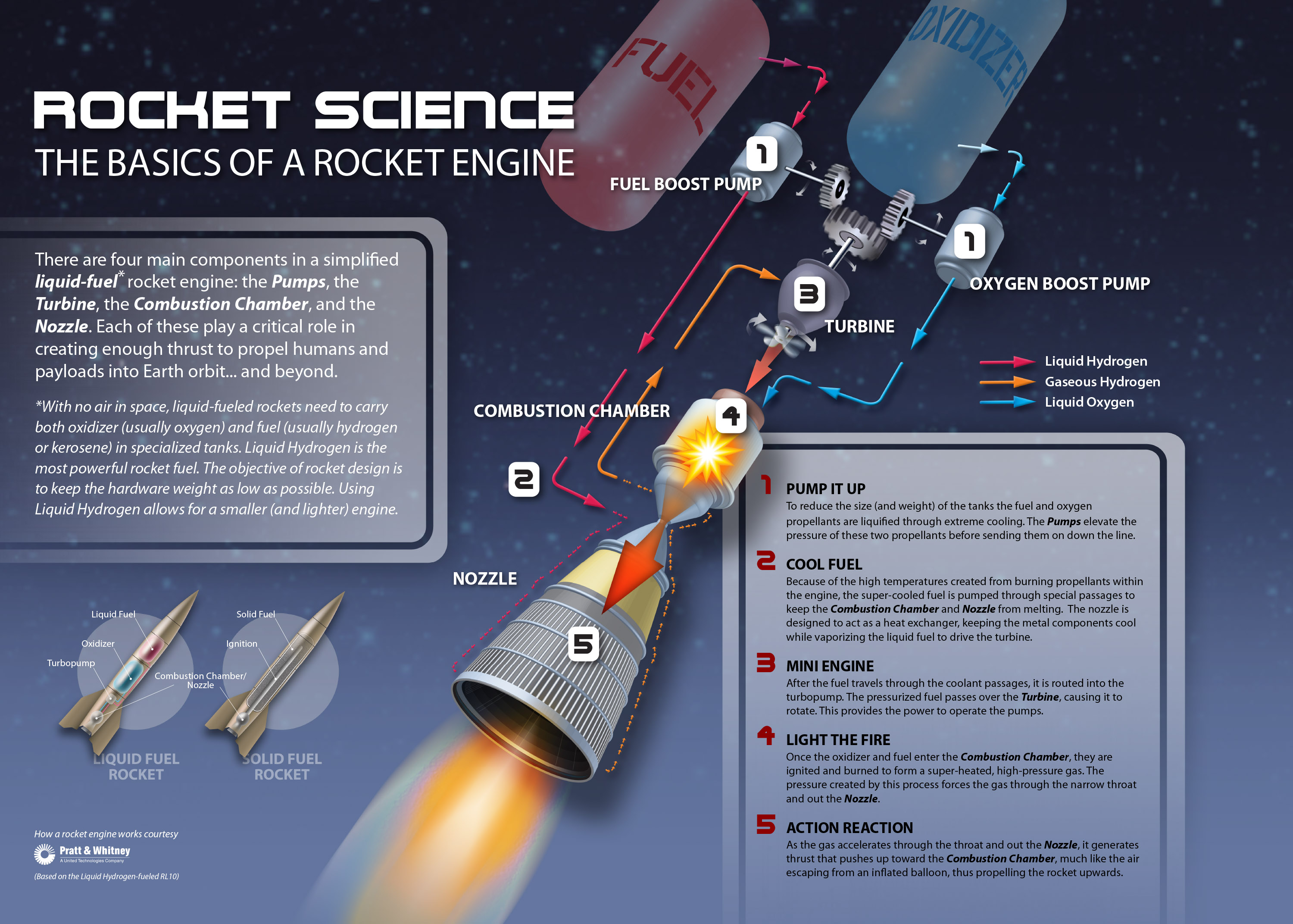


It looks like a
liquid fuel rocket engine is made of rather thin metal. Here's photo of RD-107
Ares Overview- Ares Projects(pdf)
Apollo 11 Mission Operation Report(pdf)
Hiçbir yazı/ resim izinsiz olarak kullanılamaz!! Telif hakları uyarınca bu bir suçtur..! Tüm hakları Çetin BAL' a aittir. Kaynak gösterilmek şartıyla siteden alıntı yapılabilir.
© 1998 Cetin BAL - GSM:+90 05366063183 -Turkiye/Denizli
Ana Sayfa / Index / Roket bilimi / E-Mail / Rölativite Dosyası
Time Travel Technology / UFO Galerisi / UFO Technology /
Kuantum Teleportation / Kuantum Fizigi / Uçaklar(Aeroplane)
New World Order(Macro Philosophy) / Astronomy