Elektroşok cihazı
Şok tabancaları canlıların elektrik
sistemini bozma üzerine tasarlanmıştır.
Bu silahlar yüksek gerilim düşük akım uygularlar. Yani,
bu sistem yüksek bir basınç uygulamasına karşın uzun süre bu
etkiyi göstermez. Biri size saldırdığında tetiğe basarsınız ve
silah saldırganın bedenine bu elektrik yükünü uygular. Bu
yüksek gerilim saldırganın kıyafeti ve derisinde bir etki
oluşturur. Yaklaşık 3mA civarındaki bu yük (düşük bir akım
yani) saldırganı durdurmakla beraber vücudunun da büyük hasar
görmemesini sağlar. Tabi ki uzun süre bu etkiye maruz kalmazsa.
Saldırgan şu iki mantık dahilinde etkisizleştirilebilir.
1- Bu şok cihazı sayesinde saldırganın beynine birçok sinyal
gönderilir ve beyin şaşkın bir hale getirilir. Tıpkı telefon
hattına bir akım verildiğinde nasıl ki konuşulanlar sadece bir
gürültüden ibaret olarak duyulabiliyorsa, beyin de bu
sinyaller sonucu durumu algılayamayarak kaslara anlamsız
sinyaller gönderir ve kısmi bir felce sebep olur.
2- Saldırganın vücuduna vücudun kendi sinyallerine benzer
şekilde sinyaller gönderilerek kasların sürekli olarak
çalışması sağlanır. Dışarıdan bir şey gözükmese bile bu kadar
çok çalışmadan dolayı yorgun düşen kaslar bir süre hareket
edemeyecek derecede enerji harcarlar. Saldırgan bu sayede
etkisiz hale gelmiş olur.
Bu işin temel mantığı vücuttaki kaslara ve sinir hücrelerine
elektrik uygulamaktır. Vücudun tamamı bu hücrelerle dolu
olduğundan nereye uygularsanız uygulayın vücuttaki bütün
yerler bu saldırıyı sonuna kadar hissedecektir. Şimdi şok
tabancalarının en önemlilerini ve bu enerjiyi insan vücuduna
nasıl boşalttıklarına bakalım.
STANDART ŞOK TABANCASI
Geleneksel şok tabancası son derece basit bir tasarıma
sahiptir. Bir el feneri büyüklüğündeki bu şok tabancası
sıradan 9V luk bir pille çalıştırılmaktadır.
Bu pil çeşitli elektriksel ekipmanlara sahip olan bir devreyi
beslemektedir. İçinde elektriğin gerilimini yükseltip akımını
alçaltan transformatörler bulunmaktadır. 20.000V ve 150.000V
seviyeleri genel olarak kullanılan seviyelerdir. Yine devre
içinde özel sinyallerin oluşturulmasını sağlayan osilatörler
yer almaktadır. Bu elektriksel sinyaller bir kapasitörü
beslemekte bu kapasitörler de üzerlerindeki elektriği
elektrotlar vasıtasıyla dışarı ileterek sistemi
tamamlamaktadırlar. Aşağıda bu sisteme ait resim ve devreler
görünmektedir. Elektrotlar basitçe; aralarında belirli bir
boşluk bulunan iki iletken metal tabakadan oluşmaktadır.


Resimlerden de görebildiğiniz üzere bugünkü şok tabancalarında
2 çift elektrot bulunmaktadır. Bunlardan ikisi test elektrotu
olurken, diğer ikisi (dıştakiler) boşaltıcı elektrotlar olarak
kullanılmaktadır. Eğer ki dıştaki bu elektrotların arasında
iletken olmaksızın (yani saldırganın vücudu) tetiğe basarsanız
içteki test elektrotları arasında elektrik iletimi olacaktır.
İç elektrotlar arasındaki mesafe elektrik akımının bir
taraftan diğerine sıçrayabileceği mesafede ayarlanmıştır. Bu
kasıtlı olarak tasarlanmış bir sistemdir. Saldırgan siz tetiğe
bastıktan sonra bu elektrik akımını görecek ve çıkarttığı sesi
fark ettikten sonra saldırıdan vazgeçebilecektir. Yok, hala
saldırırsa bu sefer dış elektrotlar vücuduna temas ederek
saldırganı etkisizleştirir. (bu arada dış elektrotlar arası
mesafe sıçramaya yeterli bir mesafe değildir.)
Çalışma Prensipleri
Elektroşok silah teknolojisi vücudun kas-tetikleme mekanizmaları geçersiz kılmak için geçici bir yüksek gerilim, düşük akım elektrik deşarjı kullanır. Alıcı elektroşok cihazına teller ile bağlı iki metal prob aracılığıyla tesbit edilir. Alıcı bir elektrik akımı uygulanırken bir ağrı hissedebilir ve anlık felç olabilir. Vücudun daha hassas bölgelerine elektroşok cihazları uygulanırsa daha da ağrı verici olduğu bildirilmektedir. Şok tabancası için maksimum etkili alanlar göğüs kafesinin altı, omuzun üstü, kalçanın üstü vardır. Yüksek gerilimler kullanılır, ancak çoğu cihaz öldürücü olmayan akım kullandıkları için, ölüm genellikle oluşmaz. Ortaya çıkan "şok" kas spazmları olarak görünen kontrolsüz kas seğirmeleridir.
Elektroşok silahları iç devreler, oldukça basit osilatör , rezonans devresi (bir güç çevirici ) ve yükseltici trafo veya bir diyot - kapasitör gerilimi çarpan alternatif yüksek gerilim ve geçerli deşarj sağlar. Pillere ve modele bağlı olarak bir veya daha fazla güç olabilirı. Çıkış voltajı 100 V ile 6 KV aralığında olduğu iddia edilmektedir; akım şiddeti çıkışı 100-500 mA aralığında olduğu iddia edilmektedir; Bireysel darbe süresi 10-100 ms (mikro) aralığında olduğu iddia edilmektedir; impuls frekansı 2–40 Hz aralığında olduğu iddia edilmektedir verilen elektrik şarjı 500 MCU (15mC ila aralığında) ; Verilen enerji 0,9-10 J aralığında olduğu iddia edilmektedir. Bu hedef ile temas üzerine çıkış akımı elektroşok silahı iç devresi, deşarj dalga ve pil şartları hedef direnci, cilt türü, nem, vücut tuzluluğu, giyim gibi çeşitli faktörlere bağlı olacaktır.
Talimatlar ve kılavuzlarda yer alan bilgiler yarım saniye şok süresi insanların büyük ölçüde şiddetli ağrı ve kas kasılmaları duymasına neden olacağını belirtiyor. İki üç saniye şok alıcının sersemlemesine ve yere düşmesine sebep olacaktır. Ve üç saniye boyunca alıcıyı sarsacak ve en azından birkaç saniye alıcıyı etkisiz bırakacaktır.
This stun gun is
powered by a 9V battery. The transformer steps up the voltage
to about 1800V (but with very low current). A 555 timer IC is
used to generate a high-frequency output. A 1 MEG variable
resistor can also be used at the output to drop the voltage,
but this is optional. If you build this circuit, be careful,
as it outputs a high voltage. Touching the output leads will
induce a painful shock.

NOTE: Building stun guns can be very dangerous! Please use
caution.
-------------------------------------------------------------------------------------------------------------------
How it works?
A Taser functions like two-stage voltage converter. In the
first stage, the high frequency switching transformer
increases the battery voltage to several kV to charge the
capacitor. After the capacitor is charged, it powers the
second transformer by increasing the voltage to 10 – 50kV
(approx.) with the repetition rate of 5-40 Hz (approx.).
Taser Type
There are basic types of Taser: Multiplier, Thyristor and
spark gap. Multiplier Taser is made of one transformer having
voltage of higher output and it runs on DC voltage. This type
of Taser also has high-voltage capacitors and diodes and it is
for the capacitors that multiplier Taser makes loud sound. The
Thyristor type is the most efficient one. Here the voltage of
the capacitor is not high (250 – 500 V approx.) and it
functions with the aid two main components: resistive divider
(neon lamp) and diac. The spark gap guns on the other hand is
the most cheapest and ineffective stun gun. As the name
implies, it has spark gap to function and the voltage of the
battery is charged with transistor converter.
How I made my Taser
Of the three types of Tasers, I chose to go ahead with the
Thyristor because of its effectiveness. I used MOSFET
(Metal–Oxide–Semiconductor Field-Effect Transistor) to build
the voltage converter. The main reason to use MOSFET is purely
from the point of efficiency. In a push-pull converter which
is generally used in stun guns, the level reaches around 20%
whereas in MOSFET the converter gives efficiency as much as
75% with the working frequency of 80-120 kHz. I then used a
gate thyristor for the second switch along with four neon glow
lamps with the ignition voltage of 95V and the pulse
repetition rate of 30 – 50 Hz. For inverter transformer, I
preferred to use EE core based transformer keeping the middle
column cross-section of 20 – 25 mm2. The air gap of 0.5mm
thickness is place in the mid column. The primary polarity is
set to 2x12 turns of the diameter of the wire (0.4mm) while
the secondary polarity is set to 700 turns of wire (0.1mm).
The secondary polarity is wounded in multiple isolated layers.
The reason to isolate the layers is to avoid breaking the wire
enamel under high voltage. There are two electrodes in a Taser
gun. They look like a dart and are connected to the main unit
with a conductive wire.

One can power a stun gun with either six 1.5 V cells or seven
1.2 V cells. The best option is to have two cells or Li-pol or
Li-ion connecting the series. It should be note that stun gun
draws current of around 1.5 V for which the ordinary batteries
would not work in the same.
How a Stun Gun Works
When you purchase a stun gun it is important to understand the mechanics and the principles behind the operation of a stun gun. This will help you manage the personal protection device and use it most effectively for self defense.

Stun guns work to disrupt the body's electrical pulses that are sent from the brain to the limbs and other parts of the body. When a body is functioning properly, electrical signals or neurotransmitters are sent from the brain to make every function occur which includes smiling, touching, moving your arms, legs, control over your bladder, talking, and everything else your body needs to do. Stun guns send 1-3 milliamps, which disrupt the body's electrical system causing it to temporarily shut down.
What happens when stun guns are used is that the body is temporarily paralyzed because the signals from the brain to the various muscles are being disrupted. The brain is confused and shuts down for a moment. When a stun gun works it tells the body to shut down for a short period of time. Because of all this confusion the muscles start to work extremely hard trying to figure out what they are supposed to be doing. This takes a great deal of the energy from the body by depleting the blood sugar in the body and incapacitating the attacker for a short period of time.
Stun guns use 9 volt batteries or are rechargeable. They have internal transformers designed to increase voltage and reduce the amperage that is passed into the body. An oscillator is integrated into the circuitry which works to produce the pulsing action. The charge is built up with a capacitor and the electrodes are responsible for delivering the charge. These are the only elements of a stun gun. Stun guns send voltages ranging from 200,000 to 1,000,000 or more. This is more than enough to go through the thickest of jackets and clothing. Only 3 milliamps of current are used which is why there is never any long term damage to the body.
The great thing about stun guns is that when the current is unable to flow across the double electrodes in the top, the current will go to the two test electrodes. They are close together which allow the flow of energy to leap between each of them. As the current moves it ionizes the air particles and results in a spark that is visible. You can also hear a loud crackling noise that is very intimidating. The purpose of this is so that an attacker can see that you have a stun gun. Usually the visible sign of the electrodes sparking and the sound of the crackling is enough of a deterrent for personal protection. Most attackers will go away.
Stun guns are very basic. There are many different types of stun guns and they come in many shapes and sizes. However, they all use a 9 volt battery or are rechargeable and have the same capabilities to send 3 milliamps into the body and disable the electrical signals or neurotransmitters being sent from the brain. The body will be temporarily disabled for a short period of time.
Keep in mind that when stun guns are used, the electrodes have to be touching the assailant. They are very effective in disabling a person and temporarily paralyzing them. You cannot kill someone when you use a stun gun on them. Also, the voltage going into the attackers body will not pass back to you even if you are touching the attacker.

Elektroşok Cihazı...
70.000 Volt Elektroşok cihazı

Şekildeki devre ile pil geriliminden binlerce volt elde edilecektir.
Malzeme Listesi
| C1 | 10uF 25v Electrolytic | |
| C2 | 1uF 25v Electrolytic | |
| C3 | 1uF 850v | |
| R1 | 220 ohm 1W | |
| R2 | 1K ohm .25W | |
| R3 | 500K ohm preset (trimmer) | |
| R4 | 27K ohm 0.25W | |
| R5 | 100 ohm 0.25W | |
| R6 | 10K ohm 0.25W | |
| R7 | 220 ohm 0.25W | |
| D1-D8 | 1N4008 | Anything of circuit voltage spec for D1-D7, D8 should be 1N4007 or better. |
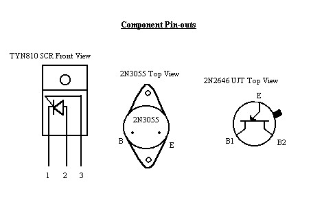
| Q1-Q2 | 2N3055 | NTE210, or any NPN transitor of about the same power rating. |
| SCR1 | TYN810 | 2N4443, or any SCR that will handle this power level. |
| UJT1 | 2N2646 | |
| T1 | ~1:75 step up | Yazıya bakınız |
| T2 | ~1:95 step up | Yazıya bakınız |
| 0.125mm ECW | Any ECW of about that size | |
| 0.25mm ECW | Anything up to ~1mm | |
| Ferrite Rod | 3+ inches long | Any ferrite rod of correct size |
| RM10 core kit | Ferrite transformer core kit | Any ferrite core of correct size, including torroidial. |
Elemanların Verileri
T1 Trafosunun Yapımı
Küçük bir ferit çekirdekli kapalı karkas üzerine sarılır. 9 volttan 675 volt almak için; 1500 tur sekonder (ikincil sargı) sarılır ve her üç primer (birincil sargı) için de 20'şer tur sarılır. Sekonder 1125 yapılıp, her bir primer 15'er tur da olabilir.
Primerler yan yana sarıldıktan sonra (0,25-0,45 mm emaye kaplı bobin teli kullanılabilir), yalıtım için izole bantla çevrilir. Bunun üstüne de 0,125 mm. veya buna yakın tel ile sekonder sargı sarılır. Sarımlar aynı yönlü olmalıdır.
T2 Bobinin Yapımı

T2 bobini, silindirik, uzun bir ferit nüve üstüne sarılır. Bu- radyolarda kullanılan bobinin çekirdeğidir veya satın da alınabilir. 0,8-1 cm. çaplı olmalıdır. 20 tur primer sargı yan yana sarılır. Üzerine 1-2 kat izole bant sarılır ve her kat yaklaşık 200 tur olacak şekilde 2000 tur sekonder sargı sarılır. Her kat arası izole bantla yalıtılır. Sekondere 0,125 mm., primere 0,25-0,35 mm. kullanılabilir.
Daha yüksek bir gerilim istenirse primer 40 tur ve sekonder toplamı 3800 tur da sarılabilir.
Çok önemli olan mesele ise katlar arası yalıtım iyi olmalıdır. Silkon veya izolasyon spreyleri de beraber kullanılabilir. Yoksa katlar arası kıvılcım oluşur ve trafo bozulabilir.
Devreyi çalıştırıken potansiyometre ile ayar yapınız. Kıvılcımın en yüksek olduğu noktada bırakın. Devreyi plastik kutuya yerleştirin ve bağlantıları çok iyi izole ediniz.
---------------------------------------------------------------------------------------------------

Do-it-yourself Stun Gun Schematic

We will present more stun gun schematics but in no way we recommend you to build it, I Assume NO LIALIBITY for any resulting actions of those persons who build or use any of these devices! This stun gun delivers 50.000 Volts and produces high voltage pulses discrupting muscles and nervous system, leaving anyone who touches it in a state of menthal confusion.
How it Works:
The schematic diagram of the stun gun is shown in Fig. 1.
Basically, it's a multi-stage power supply arranged so that
each succeeding stage multiplies the voltage produced by the
preceding stage. The final stage of the circuit feeds two
oppositely-phased transformers that produce extremely high
voltage pulses. If that description sounds familiar, you've
probably studied capacitive-discharge ignition systems--the
stun gun works on the same principles.

The first section of the power supply is a switcher composed
of Q1, Q2, and the primary windings (connected to leads E, F,
G, and H) of T1. When Fire Switch S1 is closed, R1 unbalances
the circuit and that causes it to start oscillating. Since
base current is provided by a separate winding of T1
(connected to leads C and D), the two transistors are driven
out of phase with each other, and that keeps the circuit
oscillating. Resistor R2 limits base drive to a safe value,
and diodes D1 and D2 are steering diodes that switch base
current from one transistor to the other. Oscillation occurs
at a frequency of about 10 kHz.
The switching action of the first stage generates and AC
voltage in T1's high-voltage secondary (leads A nd B). The
amount of voltage depends on the battery used, but a battery
of seven to nine volts should produce 250 to 300 volts across
T1's secondary.
That voltage is rectified by the full-wave bridge composed of
diodes D3 - D6. Capacitor C2 charges through D7 at a rate that
is controlled by R3
The value of capacitor C2 affects the output of the stun gun.
The greater the capacitance, the more energy that can be
stored, so the more powerful the discharge will be. A larger
capacitor gives bigger sparks, but requires more charging
time, and that gives it a lower discharge rate. On the other
hand, a smaller capacitor gives smaller sparks, but a faster
discharge rate. If you wish to experiment with different
values for C2, try 3.9µF (as shown in Fig. 1), 7.8µF, and
1.95µF. Those values were arrived at by using one 3.9µF
capacitor alone, two of the same in series, and two in
parallel.
PLEASE, please be careful!Meanwhile, UJT Q3 produces 15-µs
pulses at a rate of about 20ppm. That rate is controlled by C3
and the series combination of R6 and R7. When a pulse arrives
at the gate of SCR1, it fires and discharges C2. That induces
a high-voltage pulse in the primary windings of T2 to T3,
whose primaries must be wired out of phase with each other.
The result is a ringing wave of AC whose negative component
then reaches around and forces the SCR to turn off. When the
next pulse from Q3 arrives, the cycle repeats.
The outputs of the stun gun appear across the secondaries of
T2 and T3. The hot leads of those transformers connect to the
output electrodes, which should be held securely in position
about two inches apart, and which should be insulated from
each other and from the environment with high-voltage potting
compound.
Batteries:
The stun gun can be powered with almost any battery that can
supply at least 7 volts at 1 amp. A NiCad or NiMh battery
would be a good choice; R8 and J1 will allow the battery be
recharged without removing it from the case.
The higher the battery's voltage, the higher the stun gun's
output voltage. Most 9 volt NiCads actually have maximum
fully-charged output of only 7.5 volts. However, batteries
that deliver 9.8 volts when fully charged are available from
several sources.
Construction:
Keep in mind the fact that the stun gun produces dangerously
high voltages, and don't approach the construction of the stun
gun with the same nonchalant with which you might build a
light dimmer.
The circuit can be built on a PC board or on perfboard. If you
build the circuit on a perfboard, follow our parts layout
closely; otherwise you may have problems with arcing.
Due to the critical nature of the three transformers, we are
NOT providing details of winding them. They are(were)
available from the source in the parts list. Referring to the
parts-placement diagram in Fig. 2, and the photos in Fig. 3
and 4, mount all components except C2, T1, T2, and T3 on you
board. Note that several components mount on the foil side of
the PC board: C1, D7, and J1. DO not install those parts yet
either.
After all components (except those mentioned earlier) are
installed, check your work very carefully, especially D1-D6,
R1, and R3, because T1 will be installed above them, and there
will be no chance to correct errors later. After you're
absolutely sure that they're installed correctly, install T1
with the black mark on the windings mounted toward C2.
Parts List:
All resistors 1/4-watt, 5%, unless otherwise noted
R1 = 1K
R2 = 110 ohms, 1 watt
R3 = 2K2, 1 watt
R4 = 36 ohms
R5,R8 = 100 ohms
R6 = 39K
R7 = 22K
Capacitors
C1 = 10uF/25V, electrolytic
C2 = 3.9uF/350V, electrolytic
C3 = 1uF/25V, electrolytic
Semiconductors
D1,D2 = 1N4001, 50-volt rectifier
D3-D8 = 1N4007, 1000-volt rectifier
Q1,Q2 = D40D5, power transistor
Q3 = 2N2646, UJT
SCR1 = 2N4443
Other Components
B1 = 9V NiCad battery
S1 = SPST momentary pushbutton switch
T1 = 12 to 400 volts saturable-core transformer, See text
T2,T3 = 50 KiloVolt pulse transformer, 0.32 joules, 400
primary. See text
Note: The following components *used* to be available from
Information
Unlimited, P.O. Box 716, Amherst, NH 03031: T1, T2&T3(or
potted), C2,
PCB, Case, Charger, 9.8V battery, or a complete kit ($40 in
1992).
We do NOT supply any parts whatsoever for this project!
--------------------------------------------------------------------------------------------------------------------------------
Stun gun (taser)
The stun (also known as taser) can paralyze the attacker with
paralyzing electric shock. Brief contact with the stun gun
output voltage he gets an electric shock that temporarily
paralyzes him to deter further attacks. Prolonged contact with
the stun gun output voltage (more than 1s) leads to muscle
spasm, the attacker falls to the ground. Up to several minutes
he is unable to coordinated movement.
The stun principle:
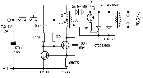
schéma zapojení elektrického paralyzéru
The schematic of the homemade stun gun (taser).
Stun gun works as a two-stage voltage converter. The first
stage with the high frequency switching transformer increases
the voltage of the battery to a higher voltage of a few
hundred volts to several kV. This voltage is charging a
capacitor. After being charged the capacitor is discharged
into the second (pulse) transformer to increase the voltage to
approximately 10 - 50kV. (Numbers on the Stun gun as 100 000 V
or even 2000 000 V are fictitious, voltage 2 000 000 V would
create discharges of more than 2m long - manufacturers are
just competing in the silly numbers of volts the general
public does not understand.) Repetition rate is about 5 -
40Hz.
Types of stun guns:
There are 3 basic types: Thyristor (SCR) ones, spark gap ones
and multiplier ones. spark gap stun guns are just the cheapest
types are very unreliable and ineffective. Thyristor is
replaced by a spark gap. Battery voltage is boosted using
transistor converter. For the ignition of the spark gap, a
higher voltage (at least 1kV) is needed and is therefore
sometimes an auxiliary multiplier is attached to the secondary
of the first voltage transformer. After charging the capacitor
to a voltage sufficient to ignite the spark gap it discharges
into the capacitor in the pulse transformer. The principle is
similar to the Tesla coil. Thyristor stun guns are more
reliable and more efficient - the spark gap is replaced by
thyristor (SCR). Capacitor voltage is not so high, just about
250 - 500V. Thyristor is driven by a diac, neon lamp or
resistive divider (for thyristor control with sensitive
electrode). multiplier stun guns have only one transformer
with a higher output voltage, followed by a high-voltage
multiplier cascade of diodes and capacitors. Their output is a
DC voltage. Thanks to the capacitors in multipliers the sparks
are very loud. In direct contact with the skin, however,
capacitors are not discharged in pulses, but continuous
current flows, which can significantly reduce the effect. It
is therefore necessary to only get the electrodes close to the
attacker body, but not touch him directly.
--------------------------------------------------------------
Electronic Dazer
By Rick Duker
Never walk in fear with this one-evening project. It won't kill, but it is an effective way to say "Leave me alone!"

Parts List
R1 = 3K3, 5%
R2 = 1M, 5%
C1 = .1µF, monocapacitor
C2-C9 = 0.01µF 400 volt polyester capacitors
D1-D8 = 1N4007, 1-kVolt diodes
NE1 = Type NE-2 neon bulb
Q1 = MJE521 NPN power transistor
Q2 = MJE371 PNP power transistor
T1 = 1200 to 8 ohm audio power transformer
S1 = SPST momentary-contact, pushbutton switch
Additionally:
9-volt battery clip, 10 x 5 x 2.5cm plastic case, 7.5 x 4cm
perfboard or pcboard, two 8/32 x 1-1/4 bolts and nuts for
electrodes, adhesive for mounting NE-1, circuit board
standoffs (optional), hookup wire, solder, etc.
WARNING:
THIS DEVICE IS NOT A TOY! We present it for EDUCATIONAL and
EXPERIMENTAL purposes ONLY. The circuit develops about 2000
volts at a respectable amperage. It can cause you pain and
even damage if you become careless and touch its output
terminals. The unit can also damage property as well so use it
wisely. You should NEVER use the device on another person! It
may not be agains the law to possess such a device in your
area, but if you use it on someone you may be deemed liable a
a civil and/or criminal action suit. Don't just follow the
golden rule after constructing the project, instead just don't
do it unto anyone. Included in the article are a number of
instructions on how to build, test, and operate the Dazer; all
of them must be followed to the letter. Do not deviate from
the procedure.
The Electronic Dazer is a modern, portable,
personal-protection appliance. It generates hight potential
energy to ward off vicious animals or other attackers. It is
an aid to help exape from a potentially dangerous situation.
the device develops about 2,000 volts. Higher voltages mabe be
attained by adding aditional multiplier stages, but it should
be noted that those stage will also increase the overal size
of the unit.
The Dazer is very compact, being built into a small plastic
case. It is powered by a single 9-volt battery, either NiCad
or alkaline. (Editor's Note: the so-called 9-V NiCad actually
provides only about 7.5V. Why? NiCad cells only give 1.25 per
cell. 6 cells in a 9volt battery gives it 7.5V and so the
Alkaline type would be a better choice).
The high voltage is applied to two electrodes which require
only light contact to be effective. When touched with the
Dazer, the victim will receive a stunning, but non-lethal jolt
of electricity that will usually discourage any further
encounters.
The electronic Dazer is apower supply which consists of a
micro-size regenerative amplifier/oscillator coupled to an
energy multiplier section. It should not be confused with a
cheap induction-type cattle prods. The Dazer is more versatile
than other high-voltage stun devices currently being sold.
Those devices are basically high-voltage, AC generators which
jam the nervous system. However, the Dazer may be used for
heating and burning applications, or anywhere a high voltage
DC supply is required.
How it Works:
Refering to the schematic diagram, the two power transistors
Q1 and Q2, form a regenerative amplifier operating as a power
oscillator. When Q1 turns on, Q2 turns on and that shorts the
power supply across the primary of T1. That current pulse
induces a high voltage in the secundary of T1. As C1 charges,
Q1 turns on again and the cycle repeats itself. Therefore, a
rapid series of DC pulses are generated and stepped up by T1
to approximately 300 volts at full battery charge. That
voltage is rectified and increased by the voltage muliplier
section which consists of C2 and C9, and D1 to D8. The final
output is approximately 2000 volts. The neon bulb NE1 is used
as a charge indicator and indicates that the unit is charge
and operating properly.
Construction:
As with all projects start out by laying out and indentifying.
If you do not wish to make a printed-circuit-board, then you
may use perf board as long as you remember to keep the leads
of all high-voltage components isolated. That is to prevent
sparks from arcing across your board. A 4 x 7.5 cm of
perfboard is suitable for that purpose.
The first components you should mount are the two transistors
Q1, Q2, transformer T1, resistor R1, and neon bulb NE1. Solder
them in place (for PCB construction) being sure that the
transformer and transistors are hooked up correctly. Apply a
small amount of adhesive to the base of NE1 to hold it
securely in place.
Mount D1 to D8 and C2 to C9 on the board and make all solder
connections. Note proper polarity of the diodes. The off-board
components come next. Solder in leads for S1, and the output
electrodes. Also solder in the battery clip for B1.
Build the enclosure from some nonconductive material such as
plastic. Drill holes for S1, NE1, and output electrodes. Be
sure that the output electrodes are about a cm or greater
apart. Connect the output wires tot the electrodes and insert
them trhought holes from inside of the case. Thread on the
retaining nuts and tighten them securely. Set the circuit
board in the case and mount S1, securing with nut. That
completes the construction.
----------------------------------------------------------------------------------
Parts List
R1 = 3K3, 5%
R2 = 1M, 5%
R3 = 10 ohm, 5%
C1 = 0.1uF, monolithic capacitor
C2-C9 = 0.01uF 400 volt polyester capacitors
Dx = 1N4001
D1-D8 = 1N4007, 1000 Volt diodes
Neon = Type NE-2 neon bulb
Q1 = MJE521 NPN power transistor (40V/40W/4A), or TIP31C
Q2 = MJE371 PNP power transistor (40V/40W/4A), or TIP32C
T1 = 1200:8 ohm audio output transformer
(green), Armaco AT-49
or Mouser part number 42TU003,
400mW $2.19, or Mode 60-282-0 at $1.81
S1 = SPST momentary-contact, pushbutton switch
-----------------------------------------------------------------------------------
Elektroşok cihazını çok farklı şekillerde yapabilirsiniz. Elektroşok cihazlarında temel mantık şudur; çok yüksek bir voltajı anlık olarak deşarj etmek. İşte işin en can alıcı kısmı bu yüksek voltajı elde etmekten geçiyor. Sonrası ise size kalmış ister bu yüksek voltajı bir kapasitöre doldurup bir insanın üzerinden boşaltırsınız isterseniz yükselttiğiniz voltajı direk olarak dayarsınız. Tabi bu durumda öldürücü olur.
Elektroşok cihazını anlatmaya başlamadan önce insan vücudunun elektriksel direncinden bahsedeyim. Çünkü bir elektroşok cihazı yapıyorsak, yaptığımız cihazın ölüm sebebiyeti içerebileceğini bilmemiz gerekiyor. İnsan vücudunun ortalama elektriksel direnci 2000 ohm civarındadır. Bu direnç akımın geçtiği vücut bölgelerine göre değişebilir. Şimdi asıl soru şu; İnsanı çarpan Voltaj mı yoksa akım mıdır? Bu sorunun cevabını şu örnekle verebilirim; Eğer insan vucudundan 20 yada 30 mA civarında bir akım geçer ise insanın hayatını kaybetme ihtimali %95 tir. Bildiğimiz gibi statik elektrikte voltaj çok çok yüksek olabilir ama bizi çarpmıyor çünkü akım yok denecek kadar azdır. İnsanın çarpılması için akım ve voltajın aynı anda uygulanması gerekiyor.
İnsanın kaslarının kasılması ve hareket sağlanması sinir sistemindeki elektriksel sinyallerin iletimi ile gerçekleşir. Bu yüzden bir insana elektrik şoku uyguladığınızda, uygulanan insan vücudu bölgesindeki kaslar kasılı kalır ve kaslara bir çeşit kıramp girer. Tabi buda ciddi ağrılara sebep olur. Bu yüzden bu cihazların kalp ve diğer vital organların yakınlara uygulanması ölümlere büyük sebebiyetler verebilir.
Bu bilgileri verdikten sonra geçelim elektroşok cihazımızın yapımına. Ne demiştik? Asıl amacımız voltajı yükseltmek. Şimdi 9 voltluk bir DC kaynağının voltajını 300 Volt DC ye yükseltmemiz imkansız. 9 volttan 300 volt output istiyorsak öncelikle transformatör kullanmamız gerekiyor. Ama transformatörler DC akımda indükleme yapmazlar bu yüzden DC voltajımızı bir şekilde A.C yada kare dalgaya dönüştürmeliyiz. Bunun için 555 timer entegresini kullanıyoruz.
Bu entegre sayesinde DC voltajımızı kare dalgaya dönüştürüp bir transformatöre uygulayabiliriz. Bu transformatörün yalıtımı iyi olmalıdır. Bu yüzden ses transformatörü kullanılabilir. Bu transformatörü kapı zillerinden çıkarabilirsiniz. Bu sayede 9 Voltluk bir D.C kaynaktan 300 yada 350 volt bir A.C voltaj elde etmiş olduk. Bu voltajın tabi kide akımı çok düşük olacaktır. Bu yüzden ister bu A.C voltajı tekrar D.C ye çevirip kapasitöre depolayın, isterseniz direk voltajı dayayın gitsin. 1. yol daha sağlam olur. Ama biz şimdilik basit yolu seçiyoruz.
Devre şemamız şu şekilde olacak;

------------------------------------------------------------------------------------------------------
ElektroŞok Silahı Yapımı
Evde bu silahı yaparak hırsızlara karşı korunabilirsiniz
Evet elektrikli , elde taşınan, bayıltıcı etkiye sahip bir
silah!
Bunu yapmak o kadar kolay ki!
Malzemeler:
*Bir fotoğraf makinasının, ayrılabilir şekilde bulunan flash
kısmı.
*Havya (tercihen 100W)
*Lehim teli
*İnce alimimyum yada bakır tel (FVV yada tercihen telefon teli)
*Yan keski yada kablo sıyırıcı ve kesici
*Tornavida
Yapım:
Kendi halinde bulunan Flash aparatanızı, tornavida ile açın.
Bu flash 2 kalem pilden daha fazla pille çalışan bir flash
olursa daha iyi olur. Daha sonra Flash Lambasının bulunduğu
yeri bulun. Buraya ya 2 yada 3 tane kablo geliyor olması lazım.
Biri lambanın üstünde diğer ikisi lambanın uçlarındadır.
Biz lambanın uçlarındakini alıcaz, üstteki, akımı toplamak ve
nötrleştirmek için. Yani bi bakıma fazla elektronları toplıyıp,
lambanın ütüne düşen gerilimi çoğaltıyor ve potansiyel farkı
çoğaltıyor. Şimdi bu uçlardaki yere biraz havya ile
ısıttığımız lehimi damlatıyoruz ve ucunu kablo sıyırıcı ile
açtığımız telleri buraya lehimliyoruz. Bunu her iki uç içinde
yapıyoruz.
Daha sonra bu kabloları flashın kabından dışarı veriyoruz ve
falshımızı tekrar vidalayıp kapatıyoruz, tabii ki bu arada o
kabloları kırılmadan dışarı çıkartmak size kalmış, yani artık
bir yere delik falan açarsınız artık, orası size kalmış. Yada
flashın ütünde bir delik bulursunuz. Kabloları çıkardıktan
sonra, dışarda kalan kısmın yarısını sıyırın. bunu her ikisi
içinde yapın ve sonra bu kısımlarısaat yönünde kıvırıp flashın
üstüne koyun. Daha sonra bir japon ile bu kabloları sabitleyin.
Tabii sizde bendeki gibi bir silikon tabancası varsa bunu
silikonlada yapabilisiniz... Bu arada bu yaptığımızın bu kadar
çok elektrik vermesi içinde bulunan Kondansatör ve trafodan
kaynaklanıyo. Unutmayın, elektriğe tutulması için birinin iki
ucada aynı anda dokunması lazım.
Peki burdaki mantık nedir?
Nasıl oluyorda 2 kalem pille çalışan bir alet bir anda bu
kadar güçlü bir etkiyle insanı çarpabiliyor?
Mantık aslında her işte olduğu gibi basit. 3V insanı
çarpamayacağına göre bu potansiyel farkını yükseltmek! bunun
yapılması ise mantık oalrak şöyle:
3V olarak güç kaynağından alınan akım, Tranzistörlerden
geçerek doğru akımdan, alternatif akıma çevriliyor. Yapılan
işlem tam olarak böyle olmasada, ihtiyacımız olan şey bu.
Çünkü bu akım çoğaltma işlemine tabi tutulmak için bir
Transformatörden geçmek zorunda. Ve Transförmatörler doğru
akımdan yükseltme işlemi yapamazlar. Çünkü Transformatörler
İndüksiyon akımı mantığı ile çalışır ve indüksiyon akımını
sağlayan şey ise sürekli değişken olan alternatif gerilimdir.
Bu aşamadan sonra indüke olarak yükselen
potansiyel fark, kondansatörler içinde hapsedilir. Burda
akımın bir kondansatör içinde hapsedilmesinin mantığı, akımın
bir anda ve şiddetle boşalmasını sağlamak. Flashlarda bulunan
"Dolma" dediğimiz bu bekleme süresi boyun bir kondansaötörün
dolmasını bekleriz aslında. Kondansatörler yarı
iletkenden yapılmıştır.
İki iletken levha arasına bir yalıtkan madde konmasıyla elde
edilen elemana kondansatör adı verilir. Yalıtkan madde "dielektrik
madde" olarak anılır.Kondansatörün kapasite değeri iletken
levhaların büyüklüğüne, levhaların birbirine olan
uzaklıklarına ve dielektrik maddenin cinsine göre
değişir.Levhalar büyüdükçe, birbirlerine yaklaştıkça,
dielektrik yalıtkanlık oranı arttıkça kapasite artar. Tersi
durumda kapasite azalır.Kondansatör, DC akımı geçirmez, zorluk
gösterir. AC akımı ise geçirir, kolaylık gösterir.
Kondansatörler; Kullanılan dielektrik maddenin cinsine göre
havalı, kağıtlı, mikalı, seramik, elektrolitik film
kondansatörler gibi isimler alırlar.
Dolan kondansatörden sonra elektrik akımı, potansiyel farkı
büyümüş halde bir kaç MiliSecond içinde boşalmaya hazır hale
gelir. Büyük bir ihtimalle o akımın boşalacağı yerde deriniz
olacaktır..
-------------------------------------------------------------------------
Bu bilgileri verdikten sonra geçelim
elektroşok cihazımızın yapımına. Ne demiştik? Asıl amacımız
voltajı yükseltmek. Şimdi 9 voltluk bir DC kaynağının
voltajını 300 Volt DC ye yükseltmemiz imkansız. 9 volttan 300
volt output istiyorsak öncelikle transformatör kullanmamız
gerekiyor. Ama transformatörler DC akımda indükleme yapmazlar
bu yüzden DC voltajımızı bir şekilde A.C yada kare dalgaya
dönüştürmeliyiz. Bunun için 555 timer entegresini kullanıyoruz.
Bu entegre sayesinde DC voltajımızı kare dalgaya dönüştürüp
bir transformatöre uygulayabiliriz. Bu transformatörün
yalıtımı iyi olmalıdır. Bu yüzden ses transformatörü
kullanılabilir. Bu transformatörü kapı zillerinden
çıkarabilirsiniz. Bu sayede 9 Voltluk bir D.C kaynaktan 300
yada 350 volt bir A.C voltaj elde etmiş olduk. Bu voltajın
tabi kide akımı çok düşük olacaktır. Bu yüzden ister bu A.C
voltajı tekrar D.C ye çevirip kapasitöre depolayın, isterseniz
direk voltajı dayayın gitsin. 1. yol daha sağlam olur. Ama biz
şimdilik basit yolu seçiyoruz.
Devre şemamız şu şekilde olacak;
Burada aslında R1=47k ve R2,R3 1k olsa çok daha iyi olur.
Görüldüğü gibi 55 entegresi sayesinde oluşturduğumuz
dalgalarla voltajımızı transformatörün secondary ucuna 300
volt olarak indüklemiş olduk.
----------------------------------------------------------------------------------------------
12V Röle bobinini kullanarak yapılan basit
şok devresi
12Volt Röle üzerinde yapılan bir kaç değişiklik ile basit bir
elektronik şok devres yapılmış. Şok devresinde ne555 entegresi
kullanılmış röle bobinine ek 0,05 mm telden 200 sipir sargı
eklenmiş. Yüksek voltajın akımı düşük fakat test sırasında
dikkatli olun sigortalı elektrik hattı ve koruyucu gözlük
kullanın.

Hiçbir yazı/ resim izinsiz olarak kullanılamaz!! Telif hakları uyarınca bu bir suçtur..! Tüm hakları Çetin BAL' a aittir. Kaynak gösterilmek şartıyla siteden alıntı yapılabilir.
© 1998 Cetin BAL - GSM: +90 05366063183 - Turkiye / Denizli
