Flaş Devresinin çalışma ilkesi...
Flaş (fotoğraf)
Fotoğraf makinesi flaşlarının çalışması için enerji depolayan araçlar kondansatörlerdir. İlk flaşlar 19. yüzyılda kullanılan barutla anlık ışık sağlayan bir düzenek idi. Ampülün ve taşınabilir pillerin yaygınlaşması, fotoğraf makinalarında ve flaş aparatında pratik gelişmeler sağladı. Ayrı bir aparat iken zamanla fotoğraf makinası ile kombine hale geldi.
Kullanım alanı
Flaş, fotoğraf çekimi için ışığın yetersiz olduğu mekanlarda ortamın aydınlatılması için kullanılır. Fotoğrafın çekilmesi için mekanın sürekli aydınlık olması gerekmemekte, tam çekim anında sağlanan yüksek aydınlık düzeyi çekim için yeterli olmaktadır. Bu sebeple flaşa bağlanmış olan kondansatör çekim anında devreye sokulur ve depolanmış yüksek enerji bir anda boşaltılır, böylece anlık olarak yüksek aydınlık elde edilmiş olur. Kondansatörde depolanan elektrik enerjisinin çoğu ışık enerjisine bir kısmı da ısı enerjisine dönüşür, ancak flaş patladıktan sonra elle temasla flaşın ne kadar ısındığına bakılıp, depolanan enerjinin ne kadar büyük olduğu anlaşılabilir. Flaşın anlık olarak biriktirilen tüm enerjiyi harcaması kondansatör sayesinde olmaktadır. Kondansatörün aniden boşalması flaş ışığının parlak olmasını sağlar. Bundan dolayı flaşlar uzun süreli yanıp, lamba olarak kullanılamazlar, çünkü sadece bir anlık parlamaları için bile ihtiyaçları olan enerji yeterince yüksektir, dolayısıyla lamba olarak kullanılmaları çok daha yüksek enerji gerektireceğinden imkânsızdır. Çok kısa süreli ancak çok güçlü ışık sağlaması fotoğraflanması zor veya imkânsız olan kareleri çekilebilir hale getirir. Bu yönüyle fotoğrafçının vazgeçilmez ekipmanıdır. Çeşitleri geniş bir yelpaze oluşturur. Temelde çalışma şekilleri çok benzer olmakla birlikte tetikleme şekilleri ve hızları değişiklik gösterir. Doğrudan makinadan, mevcut başka bir flaştan, kızılötesi tetikleme ile uzaktan, kablo ile makinadan ya da birbirine senkron yahut asenkron flaşlarla birlikte tetiklenebilir.
FOTOĞRAF MAKINASI FLAŞI ILE 220 VOLT FLAŞÖR DEVRESI
Eski hurda Fotoğraf makinelerinizin Flaş parçalarını değerlendirmeniz için basit
bir devre aslında makinelerin diğer parçalarıda iş görür şimdilik flaşör devresi
ile idare edelim devrede kullandığım triyak T1213MH flaş yakmak için gücü yüksek
daha düşük güçde triyaklar kullanılabilir elimde başka olmadığından kullanıldı
flaşör devresinde kullanılan flaş ve bobin ucuz çin malı bir fotoğraf makina
hurdasından söküldü delikli pertinaks üzerine montaj yapıldı işcilik biraz kötü
pertinaks uygun değildi deneme amaçlı merak üzerine kurulan bir devre
DİKKAT: Devre yüksek voltaj ile çalışmaktadır dikkatli olun kondansatör
bağlantılarına dikkat edin + – kutupları ters bağlarsanız yüksek voltajda büyük
patlamalar olabilir devreyi çalıştırmadan önce Sigortalı Elektrik Hattı,koruyucu
gözlük kullanın.
Malzeme Listesi
T1213MH Triyak 1 adet
1N4007 1000 volt 1 amper diyot 2 adet
47KΩ Direnç 2 adet
2.2MΩ Direnç 2 adet
22nf 400 volt kondansatör (kutupsuz) 1 adet
1uf 400v kondansatör (kutupsuz) 1 adet
4.7uf 63 volt kondansatör (kutuplu) 1 adet
30 volt diyak 1 adet
Devre ek besleme gerektirmez 220v ..240 volt şebeke voltajı ile kullanılabilir
Kullanılan pasif eleman değerleri kıritik değil iki adet 47k yerine tek 100kΩ
kullanılabilir iki adet 2.2m yerine tek 4.7m kullanılabilir ben pc güç
kaynağındaki kondansatörleri kullandım 22nf 230v yerine 100nf 400v şebeke
filtresinden alındı 1uf ise sürücü devreden 1n4007 yerine 1n4005 1n4006 ya da
1n5408 kullanılabilir flaşın yanma süresini 2,2mΩ dirençler ve 4.7uf kondansatör
değerini değiştirerek ayarlayabilirsiniz
iki adet seri direnç kullanılma sebebi yüksek voltajlarda daha sağlıklı olması
aslında bu yöntemin teorik bir açıklaması var ama hatırlamıyorum tek direnç ile
yüksek voltajı karşılamak yerine voltajı 2 direnç ile zayıflatarak kullanmak
dirençlerin ömrü ve direnç üzerinden beslenen bölüm için iyidir denilebilir bir
çok smps devresinde kontrol ünitesinin start dirençleri bu şekilde olur.
Flaşör Devre Şeması :

flaş tüpüne giden iki kablo kondansatörün iki ucuna bağlıdır ve üzerinde 300 V( flaş tüpüne göre değişebilir) civarında bir gerilim olmalıdır. Üçüncü kablo ise tetikleme trafosundan 2000 V civarında bir tetikleme voltajı verir.
Devre ek besleme gerektirmez 220v ..240 volt şebeke voltajı ile kullanılabilir Kullanılan pasif eleman değerleri kıritik değil iki adet 47k yerine tek 100kΩ kullanılabilir iki adet 2.2m yerine tek 4.7m kullanılabilir ben pc güç kaynağındaki kondansatörleri kullandım 22nf 230v yerine 100nf 400v şebeke filtresinden alındı 1uf ise sürücü devreden 1n4007 yerine 1n4005 1n4006 ya da 1n5408 kullanılabilir flaşın yanma süresini 2,2mΩ dirençler ve 4.7uf kondansatör değerini değiştirerek ayarlayabilirsiniz
Fotoğraf Makinesi Flaşı ile Elektrik Şoku Veren Eldiven
Ewet arkadaşlar bu yazımızda eski fotoğraf makinelerinizin Flaş parçalarını
değerlendirerek yapabileceğiniz Elektrik Şoku Veren Eldiven projesi yapacağız.
Proje için gerekli malzemeler:
Fotoğraf Makinesi
Kimyasallara karşı dayanıklı eldiven.
Devre montaj kutusu. 3*2*1,5 cm
Alüminyum Folyo
2* on-off toggle switch.
Bir tane basmalı (shack) anahtar.
AA pil tutucu ve tutkal.
Havya,lehim,zil teli,keski,tornavida vb.
İlk olarak fotoğraf makinesini tornavida yardımıyla sökerek başlıyoruz. Kamerayı
açın ve üzerindeki herhangi bir elektronik devreye dokunmamaya çok dikkat edin.
Pili dikkatlice çıkarın. Metal bir tornavida yardımıyla resimde 1 numara olarak
gösterilen yerde bulunan kondansatörün iki bacağını kısa devre ettirin. Böylece
kondansatör üzerideki akım boşalmış olacaktır.
Fotoğraf makinesinin flaş devre kısmını şekilde görüldüğü gibi plastik kasadan
ayırıyoruz. Çıkarma işleminde devreye zarar vermemeye özen gözterin. Devrelerin
montajı makine markaları ve modellerinde farklı olduğu için lütfen dikkatli
olun.
Kondansatörün - ve + bacaklarından şekilde görüldüğü gibi iki adet kablo ucu
çıkartıyoruz. Çektiğimiz kablonun 220 volta dayanıklı omasına dikkat edin. Flaş
patlaması anında ortaya çıkan yüksek voltajı burada bulunan kondansatörün
bacaklarından çekeceğiz.
Elektrik bantı ile uçları açıkta tel kalmayacak şekilde izole ediyoruz. Aslında
arkadaşlar projemiz burada bitti sayılır. Bundan sonra flaş devresini kutuya
montaj ediyoruz ve kablonun iki ucunu eldivenin uçlarına yerleştiriyoruz. Bu
haliyle sistem kullanılmaya hazır. Resim çekme düğmesine basıldığı anda dışarıya
çektiğimiz kablonun uçlarında 220 volt ve yukarısında bir enerji meydana
gelecektir. Sistemi biraz daha sağlıklı ve işlevsel hale getirmek istiyorsanız
bundan sonraki adımları izleyebilirsiniz. 2 mod olarak çalışacak devre için
aşağıda bulunan devreyi oluşturacağız.

Ewet arkadaşlar resimde 1 numaralı yer kırmızı led diyotun bağlı olduğu yer. On-off
anahatarlardan birini pil ile kamera flaş devresini oluşturan resimde görülen 3
numaralı bölgeye montaj ediyoruz.
Şemada görülen To glove fingertips eldiven uçlarına gidecek olan kablo uçları.
Devreye bağladığımız flipswitch (shack anahtar) kondansatörü şarj etmek için
kullanılacaktır bu yüazden her zaman açık olacaktır. Devremizi oluşturduktan
sonra proje kutumuza montaj ediyoruz.
Proje kutumuza 4 adet delik açıyoruz. Switch çaplarına göre şekilde görüldüğü
ebatlarda delikler açıp montaj işlemini tamamlıyoruz.
Şimdi geldik test kısmına. Devrenin kondansatör bacaklarından çıkardığımız kablo
uçlarının birini eldivenin baş parmağına diğerini orta parmağa alüminyum folya
kullanarak şekilde görüldüğü montaj ediyoruz.
Devreden sabit gerilim elde etmek için sadece güç anahtarını açmanız yeterli
olacaktır.
Devre üzerinde bulunan Led diyot sürekli gerilim var iken yanacaktır.
Kondansatör bacaklarında bulunan anahtarın teki sürekli açık olup şarj olmayı
sağlayacak. Diğer anahtar ise bir kaç saniye yaklaşık 300 v çıkış vermeyi
sağlayacaktır.
|
Tensions in this
assembly reaches over 300 V and are deadly.
|
||||||||
 |
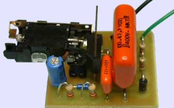
This strobe is made of recovered items in a Fuji disposable camera brand. On the photo-cons, can be recognized mainly: - A. The capacitor whose role is to store energy. - B. The flash lamp. - C. The high voltage required for booting. - D. The step-up transformer. - E. The contact of the flash. - F. The support of the R03. He noted that in this model the high voltage coil, easily visible in this photo, is integral with the lamp flash. |
|||||||
|
|
||||||||
|
Micro Flash. This strobe is designed for a small dark room. This is an educational project. To realize this setup, you will need: - The structural diagram, - The establishment of pattern components, - The artwork. To print the artwork in scale 1, uncheck the adjustment options in Acrobat. These options are not found in the same place depending on the software version. |
 |
|||||||
 |
Nomenclature : Resistance Capacitor Diac Triac Diode Flash + HT coil |
R1A, R1B R2A, R2B C1 C2 C3 U1 U2 D1, D2 FL1 |
2.2M 47 k 1 uF or 0.47 uF / 400 V 4.7 uF / 63V 22 nF / 400 V DB3 Z0409 or equivalent 1N 4007 Fuji |
|||||
| We distinguish the high voltage coil above the lamp on the left picture. | ||||||||
Manufacturing.
 When the PCB pulled, make the notch for receiving the flash. All holes are initially 0.8 mm in diameter. Then drill the diameter of 1 mm the locations of the diodes, of the triac, the flash and the coil (D). Drill 1.2 mm diameter location of C1, intended for different enclosures capacitors. 1 mm milling spindle location less flash (C). For lamp Fixings: - Drill diameter 2.5 mm the location of the pin (A) - Drilling and milling a slot at the location of the studs (B), - To set up the lamp, pay attention to the presence of clips that must be put in force. When wiring, pay attention to the polarity of diodes that are welded vertically. Applquer a layer of varnish Savings copper side to enhance the dielectric strength of the assembly. |
|
|||||||
|
Operation.
|
||||||||
 |
||||||||
|
The assembly is supplied with a voltage of 230 V AC.
Diode D2 performs a half-wave rectification. Capacitors C1 and C3 are quickly charged through R2A and R2B to the value of the theoretical peak voltage that is 325 V (A and B). The capacitor C2 charges through in-R1A and R1B resistance. When the voltage across C2 reaches 32V, the diac (model DB3) becomes conductive. The C2 capacitor discharges by creating a current in the triac trigger (via C, G, trigger, primary coil of the transformer). The triac turns on and the capacitor C3 discharges via the triac power circuit and the primary coil of the transformer. A high voltage pulse is created in the secondary of the transformer (H) which allows the initiation of the flash lamp. The capacitor C1 then discharges in the lamp by creating a flash. The energy provided by the capacitor of 1 uF is E = (C1 x V²) / 2 = (1E-6 x 325²) = 53 mJ (Voltage drops of the diodes are neglected). The power dissipated in the lamp is P = E * f = 53E-3 * 3.33 = 176 mW |
||||||||
|
When the voltage across C2 reaches the value of 32-10 = 22
V, the DIAC trigger is blocked and the current is canceled.
Then off again for a new cycle. With the values of the components of the BOM, you get a flash per second. For approximately three flashes per second, we must change the values for R1A and R1B by 470 k, R2A and R2B by 15k. The role of R2A and R2B is twofold: - Limiting the pulse current charging capacitors C3 and C1 in order to protect the diodes D1 and D2, - Avoid the destruction of the lamp only by the discharge of the capacitor C1. If the mains voltage was positive, there would be no power limitation. Two resistors 1/4 W series is put as even a very low current (R1A and R2A) does not support element 325 V. |
||||||||
 |
Oscillograms:
Calibre of the time base 50 ms / division Amplitude gauge track 1: 50 V / division Amplitude gauge track 2: 10 V / division All measurements were performed with a differential probe, respecting the standards. An unauthorized person has no right to intervene on a mounting supplied with low voltage. For these statements, the component values are: - R1A and R1B = 470 k - R2A and R2B = 15 k Lane 1 represents the voltage across the capacitor C1: The capacitor charges to the through-R2A, R2B, D2 and D1 in the positive half cycle, when the mains voltage is higher than that of the capacitor. Charging is therefore performed in several steps which are represented by the amounts of the curve segments. If the power voltage is smaller than the capacitor, the diode D1 is blocked. The voltage across the capacitor is constant, it is represented by the horizontal segments of the curve. When the triac is conducting, capacitor C1 discharges into the lamp, it is the falling edge of the curve. |
|||||||
|
It may be noted that the capacitor C1 does not have time
to fully charge, the voltage across its terminals reaching
almost 300 V. If the stroboscope is disconnected from the mains, capacitor C1 can remain loaded. For an intervention on the printed circuit, the first operation consists in short-circuiting the capacitor. Lane 2 represents the voltage across the capacitor C2: The capacitor C2 charges through in-R2A, R1A and R2B, R1B during the positive half cycle (The load curve is smoothed by the capacitor C3). Charging continues until the diac becomes conductive (32 V + voltage trigger the triac). The DIAC becomes conductive and capacitor C2 is discharged by creating a current in the triac trigger (falling edge of the blue curve). The voltage across C2 fall from a value of 10 V before the diac will re-lock (the typical characteristic is 5 V). The assembly leaves for a new cycle. With these component values, the lightning after every 300 ms. |
||||||||
|
Lamp characteristics:
1. Dimensions of the bulb: length 22 mm - 3 mm diameter 2. Voltage between anode and cathode: Minimum 200V - 300V Typical - Maximum 350V 3. Maximum Energy for a flash: 15 J 4. Lifespan: 5000 flashes (15 J if one is satisfied with an energy of 53 mJ per flash, real life is several million flashes) 5. Maximum power dissipated in one second: 6 W (P = E xf - In our case P = 176 mW, which increases the lifespan of the flash) 6. Minimum ignition voltage: 4 kV 7. Emission spectrum: 220 nm (ultraviolet) to 2 microns (infrared) with two peaks at 480 nm and 800 nm. 8. Color temperature: 6000 to 7000 ° K Exceeding the maximum caractérisiques 2 and 3 is destructive in the first flash. Exceeding the characteristic 5 destroyed bulb flash in seconds. Version: August 8, 2007 |
||||||||
Xenon flashing circuits :
![]()
This discussion
covers 3 different Xenon flashing circuits from disposable
cameras. From them, you will learn circuit tricks that have
NEVER been shown in any theory book.
The first circuit covers 6 BUILDING BLOCKS.
You will need an old "disposable Flash Camera" plus two extra
parts to carry out the modifications.
No kits are available for any of this discussion. You can get
an old camera from a friend or a photographic shop and the
parts from an electronics store. The other circuits have
different features. So let's start with the first circuit . .
. .
The first
circuit comes from a Fuji camera:

You are going
to like this project. It costs less than $3.00, contains six
BUILDING BLOCKS, re-cycles a disposable flash camera
and you are going to learn a lot about electronics.
Everyone has seen a disposable flash camera. Every supermarket,
photographic store and corner shop has them near the check-out
counter. For less than $20 you get a pre-loaded camera with a
flash! It's absolutely amazing technology, but what a waste of
resources! After 12-27 flashes, you throw away the camera and
a perfectly good flash unit.
With a little bit of fore-thought, manufacturers could have
made the camera re-loadable, but that would defeat the purpose
of disposability!
It seems such a waste, to throw away a complete high-voltage
flash unit, but that's the cost of progress.
Well, now you can take advantage of this and pull apart a USED
camera. The next time you buy a disposable camera, ask for it
to be returned to you when the store develops the film.
Alternatively you can ask the store to save the next unit that
comes in for development - after all, they throw the units
away!
For this project, all you need is a flash unit and two extra
components - a BD 679 transistor and a high speed diode. (For
a discussion on
transistor pin-outs, and finding if the transistor is
PNP or NPN, go to:
transistor pin-outs.)
You can turn the flash unit into a
REPEATING FLASHER CIRCUIT that will flash at the
rate of about one flash every 2 or 3 seconds, depending on the
quality of the battery. The flash unit draws a very high
current and only a fresh alkaline cell will be suitable. That's
the only problem with the circuit. It draws a very high
current.
Note: Although the project is written as "XENON Flasher"
the letter "X" is pronounced "Z" as in ZENON.
The brilliance in technology does not stop with the
electronics. If you look at the shutter assembly, you will
note it opens the "hole" (also called the pin-hole) as it
moves from left to right then closes it again as it moves from
right to left. This allows sufficient light to enter the
camera.
When in flash mode, the shutter opens the hole (by moving from
left to right) but the flash has not yet been triggered. The
conditions will generally be fairly dark and the film will not
been exposed. (it will not have "taken a picture") The shutter
then hits the "trigger switch" and the xenon tube flashes
immediately. This illuminates the subject and as the shutter
closes the hole, the film is exposed. This effectively give s
the camera two shutter speeds! How clever!
THE BUILDING BLOCKS
This project has 6 separate building blocks:
1. A sinewave oscillator -
more realistically called a feedback oscillator
or blocking oscillator.
2. A charge-pump - a diode charging a capacitor
3. A time-delay circuit
4. A relaxation oscillator - not used when in the
repeat flash mode
5. A transistor in breakdown mode - this is one of the
added components
6. A trigger transformer
WARNING
This project generates 350V DC and stores the
voltage in a large electrolytic. This voltage will not kill
you, but will deliver a nasty SHOCK! For this reason, the
project has a great benefit. It will teach you to work very
carefully on equipment with high voltages and if you do get a
shock, you will appreciate electricity EVEN MORE! Simply
discharge the 120u electrolytic with a screwdriver or jumper
lead before working on the circuit. I do. I'm not silly. I
don't want to get a bite or tingle each time I pick up or work
on the board.
There is no reason why beginners cannot experience working on
this project as it contains non-lethal high voltages and is a
very good grounding for electrical safety.
We forgot to mention the other high voltage produced by the
circuit. As you will learn in the notes, a trigger transformer
is also included in the circuit and it produces a very high
voltage to trigger the Xenon tube to produce a flash. This
trigger voltage is approx 2,000 volts but since it is only
present for a very short period of time, you would have to be
holding the circuit at the instant when a flash occurs, to
feel the spike. None the less, this 2kV is part of the circuit
and adds to the fact that this project is packed with features.
THE FUJI CIRCUIT

1. THE SINEWAVE
OSCILLATOR
We
start the discussion with the transistor oscillator. It's not
really a sinewave oscillator as this infers the output is a
nice, clean sinewave. It's really a blocking oscillator or
pulsed oscillator or feedback oscillator or flyback oscillator
as the high voltage produced by the secondary winding occurs
when the transistor is switched off and the magnetic flux
collapses and creates the high voltage in the secondary (also
called the tertiary or "overwind") winding. For
more details on the operation of this type of
oscillator, see our project:
"Making
your own 3v inverter."
The oscillator converts the 1.5v DC supply voltage to a 350v
AC waveform. This waveform is rectified by a high-speed diode
and charges a 120u 330v electrolytic.
The oscillator consists of three components:
1. A transistor
2. A transformer, and
3. A 220R resistor.
For an oscillator to work, it must have positive feedback. In
other words, positive feedback is a signal that encourages the
transistor to keep moving in the direction it is travelling.
This can be in the "turning-on" direction or the "turning-off"
direction. It's a bit like encouraging a cyclist to peddle
harder up hill. That's positive feedback. Then to
encourage him to peddle harder down-hill. That's also
positive feedback.
The transistor gets turned on a small amount by the
220R resistor on the base. Current flows through the
transistor and also the winding connected to the collector.
This is called the primary winding. The primary winding
produces magnetic flux and the important thing to remember is
the flux is EXPANDING FLUX. In other words the flux is getting
stronger (or more-accurately: MORE LINES OF FLUX ARE BEING
PRODUCED - THE FLUX-LINES ARE CLOSER TOGETHER).
This flux passes through all the turns on the
transformer and a voltage (and current) is produced in each
turn. There are three separate windings on the transformer, (we
really say the current is available as a current cannot
be measured until is it actually flowing):
1. The primary winding
2. The secondary winding, and
3. The feedback winding.
The feedback winding is connected between the 220R resistor
and the base of the transistor. When the transistor turns on,
the voltage produced in the feedback winding ADDS to the
voltage supplied by the resistor and this turns the transistor
on MORE.
The transistor keeps turning on HARDER until it cannot turn
on any more. The flux in the transformer is a maximum but it
is not EXPANDING FLUX. It is called STATIONARY FLUX.
Stationary flux does not produce a voltage or current in the
other windings and thus the voltage and current produced in
the feedback winding ceases to flow. This causes the
transistor to turn off a small amount and the magnetic flux in
the transformer is REDUCED. This flux is now called COLLAPSING
MAGNETIC FLUX and it cuts the turns in the transformer and the
voltage it produces in the turns is in the OPPOSITE DIRECTION.
This is one of the amazing features of a transformer. It will
produce an output voltage with positive on one wire and
negative on the other, when the magnetic flux is expanding.
When the flux is moving in the other direction (collapsing)
the output voltage is REVERSED.
This reverse voltage turns the transistor OFF a small amount
and it keeps turning the transistor off until it is FULLY OFF.
The reverse voltage from the feedback winding ceases, an the
transistor gets turned on again by the voltage and current
supplied by the 220R resistor.
This is how the cycle repeats and the oscillator operates at
approx 3kHz. In other words, this action is repeating 3,000
times per second.
2. THE
CHARGE-PUMP
The charge-pump consists of the secondary winding of the
oscillator transformer, the high-speed diode and the 120u 330v
electrolytic.
The secondary winding consists of many turns of wire (I
haven't counted them). The voltage from this winding is in the
form of a pulse or sinewave with an amplitude of about 350v.
i.e: the distance from top to bottom represents a voltage of
350v. This is fed into a diode and as we have mentioned in the
previous pages of the course, a diode only allows voltage (and
current) to flow through it when the anode is higher than the
cathode. You will notice the diode has been placed in the
circuit in the reverse direction to the way we have suggested
in the theory section. That does not matter, it works exactly
the same, except the negative pulses pass through it (because
the positive pulse emerges from the other end of the
transformer and this is really the pulse that goes around the
circuit and passes through the diode in the forward direction)
and charge the electrolytic. The electrolytic has been fitted
with the positive going to the 0v rail.
Thus, on every negative pulse (from the top of the transformer),
the voltage charges the electrolytic. If you place a voltmeter
across the electrolytic, you can see the voltage rising. It
rises quickly at first, then at small voltage increments. This
corresponds to the graphs we have covered previously, where
the capacitor charges quickly at first, then slows down as the
capacitor charges to its full value. It charges quickly at
first because the charging voltage is very high and the
opposing voltage on the capacitor is small and thus the
charging voltage has a lot of "pressure" to get the charge
into the capacitor.
3. THE
TIME DELAY CIRCUIT
The time-delay circuit consists of the 4M7 resistor and 22n
capacitor.
In the original design, these two components form a time-delay
circuit to let the user know when the storage electrolytic has
reached full voltage. The 22n charges via the 4M7 and when 65v
appears across it, the neon lamp produces a pulse of red light.
4. THE
RELAXATION OSCILLATOR
The neon just doesn't produce a constant red
glow, it flashes at about 1 flash per second. The lamp flashes
when the voltage across the 22n reaches 65v and keeps glowing
until the voltage falls to about 45v. It then goes out. The
22n charges up via the 4M7 and the lamp flashes again when the
voltage reaches 65v. The 4M7, 22n, neon lamp and 10k form a
relaxation oscillator with the voltage across the 22n ranging
between 45v and 65v. The 10k resistor prevents the voltage
across the 22n falling too low and has an effect on the flash-rate. If
you look at the waveform on a CRO, it will be similar to a
sawtooth. We are not using this waveform for any purpose in
this project, it just happens to be a very simple way to
illuminate the neon lamp with the least possible energy, so
the main circuit is not "bled" of too much energy.
5. THE
TRANSISTOR IN BREAKDOWN MODE
Our project takes advantage of the fact that a transistor will
breakdown when sufficient voltage is present across the
collector-emitter terminals and restore its high impedance
when the voltage is removed.
We have added a second high-speed diode to the output of the
transformer. This has been done to pick up the positive pulses
from the transformer.
the purpose of this diode is to charge the 22n as fast as
possible to a very high voltage to breakdown the transistor
connected to the primary of the trigger transformer. The
transistor happens to be a darlington type but this is not
necessary. Almost any transistor will perform however its
current-handling capability needs to be high die to the heavy
spike of current delivered by the 22n to the transformer.
The point at which the circuit "triggers" or "fires" depends
on the breakdown voltage of the transistor. The transistor is
rated at 80v between collector-emitter but the actual
breakdown effect does not occur until about 280 - 300v.
We need to get the voltage up to this value as soon as
possible so that the trigger transistor will "fire" and ionise
the tube ready for a flash.
6. THE
TRIGGER TRANSFORMER
The energy stored in the 22n capacitor is
passed to the trigger transformer when the transistor breaks
down. The 22n will have about 300v across it and this voltage
is delivered to the primary of the trigger transformer via the
BD 679 transistor. The secondary has a large number of turns
and the transistor delivers a pulse of energy to the primary.
This pulse of energy lasts only a very short period of time
and the magnetic flux builds up and collapses. The collapsing
flux produces a very high voltage (approx 3,000v) in the
secondary and this is passed to a plate at the back of the
Xenon tube (in our case the reflector is the "backing plate"
and it effectively ionises the gas in the tube by generating a
voltage gradient between the outside of the glass tube and the
gas inside and it becomes a very low resistance. The 180v on
the electrolytic is also on the ends of the tube and the
energy in the electro is instantly delivered to the tube. The
result is a brilliant white flash.
MORE ON
THE "CIRCUIT"
Unfortunately this project cannot be left in a "ready" state
as the circuit consumes about 250 - 300mA just to keep the
electrolytic charged and a single cell will last only a few
hours. Once the electrolytic is charged, it will remain
charged for a long time, provided the neon tube is taken out
of circuit, as it "bleeds" off a small current through the 4M7
and will keep flashing until the voltage reduces to about
100v. If you can design a circuit to turn the oscillator on
and off, to keep the electrolytic charged, it can be kept "ready."
Otherwise it will have to be "fired up" every time it is
needed. This will only take about 15 seconds or so and it can
be used in an alarm project to indicate when the alarm has
been triggered. Normally a blue strobe light is used, but the
circuit can take its place, provided the supply is kept to
between 1.5v and 2v.
DIFFERENT CIRCUITS
Unfortunately not all flash units are
the same. Our flash unit was taken from a FUJI camera and even
different model cameras may have a different circuit.
The only thing you can do is try the modifications outlined in
this project and see if they work. Otherwise you will have to
carefully get the circuit off the board and compare it with
the one we have drawn. The basic operation of all flash units
is the same. One of the possible differences is the positive
or negative charging of the storage electrolytic.
GETTING
THE CIRCUIT "OFF THE BOARD"
If your flash unit does not work after you have added the
transistor and resistor, you will have to check to see if it
is the same as ours.
This will involve getting the circuit off the board. This is
not easy and not difficult, it just requires a lot of patience
and care.
There are two things you need to know before starting - to
make the process much easier - the symbol for each component
and an approximate layout for the diagram. In this case the
layout and components will be almost identical to the circuit
we have provided. The only difference may be the orientation
of the high-speed diode and electrolytic. If these are around
the other way, the switching transistor must also be placed
around the other way.
You can start anywhere on the board. Turn the board back and
forth to make sure you can see where the leads are going
through the board and follow the tracks from one component to
another. Check everything over and over to make sure you
haven't made a mistake. It's so easy to think a track connects
to a particular component whereas it connects to an adjacent
component.
If you don't know the symbol for a particular component,
sketch its outline and draw the leads on the sketch. Later you
may be able to identify the device by the value of the
surrounding components.
POWERING
THE FLASH UNIT
If the flash unit is powered by an external
power supply, you will have to keep the voltage between 1.5v
and 2v so that the oscillator transistor is not over-driven.
With many types of electronic devices, the circuit will
consume a considerably higher current if the voltage is
increased slightly. This is due to many factors, one of which
is the saturation of the transformer when a higher voltage is
applied. The higher voltage will cause a higher current to
flow and this will produce a higher flux density. The
transformer may not be able to accept a higher flux density
and the result is additional current is drawn by the circuit.
The higher current may damage the transistor.
In addition, the higher voltage will produce a higher "back
voltage" (called back emf) and this voltage is in the
form of a spike that can puncture the transistor. In fact a "power
transistor" is more likely to be instantly damaged by a spike
than by overheating.
If you want to add a larger cell, the most economical cell is
size "D" (called the normal torch cell). Placing two or more
cells in parallel will increase the time the circuit will
operate.
Fitting a 6v battery and using diodes or resistors to drop the
voltage is a very uneconomical way to power the circuit. You
will get no more life out of the four cells in a lantern
battery than using a single "F" cell.
USING
THE PROJECT
The project can be used as a "dummy camera" to scare intruders.
Using a mercury switch on the input, (or an ordinary switch)
will turn the unit on.
A RELATED
PROJECT
If you like oscillators and high voltage, a similar
project is: "Making your own 3v Inverter." It is a 3v inverter
that produces a high voltage (approx 120v) to drive an
electroluminescent panel or length of electroluminescent "rope"
or "string." More details of this project can be found
HERE.
CHANGING THE FLASH-RATE
One of the requests for this circuit was to increase the flash-rate.
The order came to Stelar Laboratories to supply 70 flashing
Batons for the Gay Mardigras. The Fuji circuit was the best of
the three circuits to use as it has the fastest charge-circuit
and the flash rate was increased by reducing the value of the
reservoir electrolytic. By reducing the capacitance of the
main reservoir electrolytic, it will be charged faster to the
level detected by the neon and the flash-rate increases. We
simply put another 120u in series with the first electrolytic
to get 60u.
It is interesting to note that the 4M7 charging resistor can
not be decreased below 2M2 as the circuit will stop working.
Why is this?
The reason is simple. The trigger transformer relies on
receiving a pulse of energy into the primary and the
collapsing magnetic flux produces the high voltage.
If the feed resistor is too low, a current continues to flow
in the primary and the magnetic flux does not collapse!
Photos to
come for this article!
CIRCUIT
2: THE KODAK CIRCUIT
The next circuit we will study comes from a Kodak camera. This
has a number of very clever features. Firstly, the circuit is
an automatic charger. It charges the 120u electrolytic then
switches off. This increases the life of the battery
considerably as the circuit is only powered for 15 seconds or
so for each picture and there is no need for an on-off switch.
The switch on the circuit is a "start" switch. The circuit
also charges up the electrolytic again, after the picture is
taken, ready for the possibility of another photo. This action
occurs merely because the circuit is "upset." The camera
actually gets left with the electrolytic fully charged and it
is gradually discharged through natural internal leakage.
We can only describe the circuit "in general" and cover some
of the clever features because the actual operation of the
circuit (its efficiency, for example) is a product of the the
size of the transformer and the gauge of the windings (especially
the primary winding) and the characteristics of the
transistors. Some types of transistor work better than others
and this may be due to current handling ability or maximum
operating voltage (zener properties) or the gain of the
transistor.
For example, this circuit takes 4 times longer to charge a
120u electrolytic to 260v, than the first circuit, due to the
transformer being much smaller, (the primary winding is much
thinner), and the frequency of operation is much lower.
The supply voltage is 6v and the current consumption is about
300mA.
A high supply voltage has an advantage. The supply rail can
fall a certain amount before the performance of the circuit
reduces. In addition, the current requirement from each cell
is less.
For a 1.5v supply rail, the voltage cannot drop by more than
0.5v before the performance of the circuit reduces.
In addition, the 1.5v circuit draws over 1 amp when a low-impedance
cell is connected. An alkaline cell is a low impedance cell
(it can deliver a very high current) and the flash rate is
noticeably higher when this type of cell is connected.
All of these circuits are intended for intermittent use and
the current requirement is of little concern, but if you want
a circuit to use most of the energy of a cell, the current
consumption must be kept as low as possible.
All battery ratings are taken at a few milliamp (for AAA and
AA cells the current is between 10 and 50mA) for C and D
cells the current is about 100mA) and the cell is only used
for a few hours per day then rested. When the terminal voltage
of a cell falls to 0.9v or 0.7v the test is terminated. The
multiplication of the current and number of hours of operation
is multiplied together to get the amp/hr capacity.
You can see that these represent very light duty and if the
requirements are increased, the capacity of the cell is
reduced.

HOW THE CIRCUIT
WORKS
The Kodak circuit is fully automatic. The "start" button is
pressed and this turns on an NPN transistor via a 2k resistor.
The circuit begins to oscillate and the voltage from the
feedback winding gets superimposed on the DC voltage from the
start switch to keep the circuit oscillating. The button can
now be released and the circuit will keep operating.
Each time the feedback winding produces a pulse, it charges
the 100n capacitor and this puts a negative "set" on the base
of the second transistor. If this negative voltage gets too
high, the pulse from the feedback winding will not be able to
turn the transistor ON and the circuit will stop. This is
fully discussed in another article "Making
Your Own 3v Inverter." The 100n is constantly being
discharged by the first transistor and this transistor is
turned on via a pulse from the high-speed diode. As the main
storage electrolytic gets charged, the pulses entering it get
smaller and smaller. Eventually the pulses are so small that
they do not pass through the 330p capacitor and the first
transistor is not turned on. This causes the 100n to charge
negatively and after a short time the oscillator circuit is
prevented from beginning a cycle - and it stops. The 120u is
fully charged and some of the high voltage is bled into the
neon lamp circuit to illuminate the lamp. This lamp only takes
a fraction of a milliamp to create a red glow and the operator
of the camera is informed that the camera is ready for use.
The 33n storage capacitor is charged and when the trigger
switch is activated by the shutter, the energy from the 33n is
passed into the primary of the trigger transformer to create a
very high voltage across the ends of the flash tube to ionise
the gas within the tube and allow it to flash.
If you study the circuit in the off state, you will find
absolutely no current paths and thus the circuit consumes no
current when at rest. The first transistor is kept off via the
330k and 220k. This keeps the second transistor off and the
second transistor keeps the third transistor off. The LED is
reverse-biased when the circuit is at rest and thus no current
is consumed.
The repeat-flash components can be added to the Kodak circuit,
exactly as above.
There is probably a dozen or more "tricks" in the design of
this circuit that is not evident on a simple circuit diagram.
You have to have the PC board in your hand to see how the
flash tube has a shield around the rear surface so the voltage
from the trigger transformer is able to ionise the gas in the
tube.
The 330p detecting the pulses from the charging circuit is a
high voltage type and the 120u electrolytic is a special "photo"
type that can be discharged very quickly without being damaged.
The rest of the tricks lie in the design of the oscillator
transformer and trigger transformer.
If you are going to design a circuit similar to this, you must
start with a circuit that works and change one component at a
time. By choosing a value higher or lower you will be able to
determine how much effect it is having on the circuit.
This technique applies to all forms of circuit design. Start
with something that is guaranteed to work and make small
modifications.
Now we will see how another design engineer tackled the flash
circuit:
CIRCUIT
3: THE AGFA CIRCUIT
This circuit takes a slightly different approach to the job of
flashing a Xenon tube in a disposable camera.
It has a couple of different features and shows how you can
tackle the same problem in a different way.

HOW THE CIRCUIT
WORKS
The circuit is turned on by a "start" button that puts a small
DC voltage (from the 1.5v DC supply) into a 100u electrolytic.
The voltage across this electro is passed to the base of an
NPN transistor and this causes the collector-emitter leads to
have a low resistance. This turns on a PNP transistor and the
PNP transistor delivers current to the main oscillator
transistor. The oscillator stage now looks almost exactly like
the oscillator stage of circuit 1. The circuit will start-up
quickly and the operator will not have time to release the
"start" switch before the waveform on the collector of the
oscillator transistor is able to pass spikes of energy into
the 100u via the diode.
This will give the electro added voltage so that the circuit
stays on long enough to charge the 120u 330volt electrolytic
for the flash tube.
The 100u in the time-delay circuit (also called the start-up
circuit) is gradually discharged by the 330k (and also the
220k) and these are designed to turn the circuit off
completely.
An indicator LED is included in the circuit and you will
notice it is up-side-down to what you would expect.
As the voltage across the 120u electrolytic reaches 260v, the
magnetic energy in the transformer is not required by the
electrolytic and larger negative pulses develop. These pulses
are fed to the LED via the 150R resistor and the LED begins to
illuminate.
The circuit shuts down to absolutely zero current via the 330k
bleed resistor removing all the voltage from the 100u
electrolytic.
The first transistor is said to be in a 'high impedance"
arrangement so that it bleeds very little from the 100u while
it is keeping the rest of the circuit active.
The 150R on the emitter is forming a dual task and needs
describing.
The aim of the circuit is to get as much charge into the 100u
as possible so that the circuit stays on for as long as
possible.
When the circuit turns on, current flows through the 150R and
this causes a voltage to develop across it to raise the
emitter. This means the base will be higher and thus a higher
voltage is needed on the base to keep the transistor turned
on. This is not a problem but the advantage is the transistor
draws less current (bleeds less current) from the 100u and so
the delay time is extended.
The other (and main) reason why the resistor is added is to
raise the voltage on the collector of the first transistor so
that the second transistor can turn on the oscillator
transistor.
With out the resistor, the first transistor can "pinch off"
the oscillator transistor because the voltage between the
collector and emitter of the first transistor can go as low as
0.3 to.0.5v and this is below the turn on for the base of a
transistor.
ADDING THE
REPEAT FLASH
Our modification to create a repeating flasher can be added to
this circuit. See the BD 679 transistor added to the Fuji
circuit above.
Hiçbir yazı/ resim izinsiz olarak kullanılamaz!! Telif hakları uyarınca bu bir suçtur..! Tüm hakları Çetin BAL' a aittir. Kaynak gösterilmek şartıyla siteden alıntı yapılabilir.
© 1998 Cetin BAL - GSM: +90 05366063183 - Turkiye / Denizli
