Telegraphy
Two hundred years ago or so, messages could only be sent by some form of noise, flare or beacon, or by actually transporting it. It was not until people learned how to send transmit messages by electricity that a whole new era in communications was opened up. A telegraph is an electrical apparatus for sending coded messages. The term was first applied to Claude Chappe's semaphore.

Samuel Morse transmits a message by telegraph. Behind him is the receiver on which the message is recorded.
Experiments began on electric telegraphs after the discovery (1819) that
a magnetic needle was deflected by a current in a nearby wire. In 1837 W. F.
Cooke and Charles Wheatstone patented a system using six wires and five
pointers which moved in pairs to indicate letters in a diamond-shaped array.
It was used on English railroads. In the same year Samuel Morse, in
partnership with Alfred Vail, and helped by Joseph Henry, patented a
telegraph system using Morse code in the US. The first intercity line was
inaugurated in 1844. At first the receiver embossed or printed the code
symbols but this was soon replaced by a sounding device. In 1858 Wheatstone
invented a high-speed automatic Morse telegraph, using
punched paper tape in transmission. In 1866 the first permanent telegraph
cable was laid across the Atlantic The TELEX system, using teletypewriters,
became the most popular. In 1872, Jean-Maurice-Émile Baudot invented a
multiplexing system for sharing the time on each transmission line between
several operators.
The science of early telegraphy
Telegraphy is based on the sending of electrical impulses through wires.
An electric current can easily be sent through a wire by a battery, and the
duration of the current can be controlled by switching the battery on and
off. The wires at the other end can be connected to a receiver – an
electromagnetic instrument designed either to make a sound like a buzz or a
click, to ring a bell, to alter the direction of a magnetic needle, or draw
a line.

This diagram shows the simplest possible telegraph circuit in which messages can be transmitted in one direction only.
The first ever telegraph system was set up in London in 1837 by Charles
Wheatstone. His earliest system was very cumbersome, using five different
lines, and he soon replaced it with a single-line system. The receivers of
these early systems worked by deflecting magnetic needles.
While these advances were being made in Britain, Samuel Morse was developing
his own telegraph. In his apparatus, which was first used in 1844, the
electric current worked an electromagnet that caused a pencil to mark a line
on a moving piece of paper. By regulating the length of the electrical
impulses, Morse was able to produce long and short marks. He invented a code
in which combinations of these long and short marks, known as dots and
dashes, represented the letters of the alphabet.
A simple telegraph set consists of a battery to provide the electric
current, a wire or line to carry it to another place, a sending switch or
'key', and a receiving instrument. The current must return to the battery to
complete the circuit, and it is often arranged for it to return through the
earth. This is called an earth return.
The instrument which sends out the signal is called the transmitter.
In a manual telegraph the impulses are controlled by the Morse key,
a small metal arm with a contact at each end and a pivot at its center. When
the key is pressed the contact at its front end touches another contact
immediately below it on the base board, thus connecting the battery to the
line, completing the circuit, and allowing current to flow to the receiver
at the other end. When the key is not in use for transmitting, the contact
at its rear end touches the contact immediately below it and connects to a
receiver any signals being transmitted back along the line.
 |
| Pens used for recording telegraph signals
|
 |
| A word spelled out in Morse
|
Early telegraph receivers had magnetic needles, which were deflected from a
center line as each impulse arrived from the transmitter. But this meant
that the person receiving the message had to watch the dial at the same time
as writing down the message, and, as a result, these receivers were soon
superceded by ones that emitted sounds. Short and long impulses on these are
distinguished either by two different sounds or by the time that elapses
between the sounds. Other receivers, like Morse's, draw dots and
dashes with pens controlled by electromagnets.
Duplex, quadriplex, and multiplex
Telegraph circuits were costly to install an d operate, and so man
devices were invented to increase the message-carrying capacity of
individual lines.
In the duplex system a single line carries two messages at
the same time, one in each direction. This is achieved by connecting both a
transmitter and a receiver at each end of a line. In the more complicated
quadriplex system two messages can be sent from each end at
the same time. The complicated multiplex system can handle
four or more messages at a time.
A rather different way of increasing the capacity of a telegraph line is to
feed into it a number of electric 'current' currents of different
frequencies. Telegraph signals can then be superimposed on each of these
carriers. The signals can be sorted out by filters at the receiving end and
then routed to separate receivers for decoding.
Radiotelegraphy
Telegraphy between cities, and between countries separated by sea, was
usually carried out by means of land-lines and submarine cables. This method
was obviously impossible for ships at sea, and was therefore replaced by
telegraph signals sent by radio (radiotelegraphy). Radiotelegraphy
is less affected by distortion than radiotelephony (voice
transmission), and could therefore be used when distance or atmospherics
make satisfactory radiotelephonic contact impossible.
Automatic transmission
|
|
| The head of an automatic transmistter
used for tape with two lines of holes. |
table> A skilled operator using a Morse key could transmit about 40 words
each minute. A telegraph line could handle many more, so a single line could
carry a great many messages if transmission and reception were speeded up.
This was done by automatic transmission.
Messages to be transmitted were first encoded on a narrow tape of paper. The
early code was based on the Morse Code, and a simple device punched two
lines of holes in the paper. Two holes, one immediately above the other,
represented a short impulse or dot; two holes, with the lower one to the
right of the upper, represented a long impulse or dash. The completed tape
was fed through a transmitter operating at several hundred words per minute.
Since the transmitter could deal with tape much faster than it could be
prepared, several people could use a single transmitter and line. Equally
fast machines were needed to receive and record the signals. These were
chiefly reperforators that prepared from the incoming impulses tape
exactly like that fed into a decoding machine that produced a second tape on
which the message was printed in Roman characters.
Later most automatic transmission systems used tape punched with a five-unit
code, two of the holes being above and three below a line of feed holes.
This system was used chiefly for transmission in submarine cables and for
teleprinter services. The tape was prepared on a machine with a keyboard
like a typewriter, or on a teleprinter with a special attachment. On receipt
it was decoded into words in a single step, either on to a ticker tape or on
to a paper roll.
Teleprinter
 |
| Teleprinter |
The teleprinter, or, as it was called in the US, the teletype writer, is
an instrument used both for the transmission and the reception of telegraph
messages.
The teleprinter had a keyboard much like a typewriter. When the operator
pressed a key a code combination of five units representing the letter was
sent down the line to the teleprinter at the other end. This signal caused
the second teleprinter to select and print the same letter on a paper
ribbon.
Teleprinters could transmit directly. It was also possible to record
messages on a punched tape that could then be fitted to an attachment on the
teleprinter. In this way a number of messages could be prepared in advance
and then transmitted without a break.
The advantages of teleprinters were that they could receive messages when
they were unattended at night, and that they provide permanent written
records of business arrangements that have been completed with their aid.
In many countries special telegraph networks were available to connect
teleprinters. Other systems connected teleprinters to each other through the
ordinary public telephone exchange.
TELGRAFIN TARİHİ
Telgraf elektrik akımını kullanan ilk haberleşme aracı
olması ile önem kazanır. O zamanlarda, haberleşmek için
telgrafa alternatif sadece mektuptu.
1830 lu yıllarda elektrikle haberleşme
sistemi için gerekli tüm öğeler hazırdı: Elektrik akımı,
manyetizma ve elektromanyetizma. Şimdi tüm bunları birilerinin
birleştirip, haberleşmeyi sağlayacak sistemi geliştirmesi
gerekiyordu.
1830 yılında Amerikalı Joseph Henry (1797-1878), elektrik
akımını teller vasıtasıyla uzaklara taşıyıp, oradaki bir zili
çalıştırdı. Zil bir elektromıknatısa bağlıydı. Bu elektrikli
telgrafın doğuşuydu.


1832 yılında Amerikalı ressam Samuel Morse, bir yolculuk
sırasında kendisine elektromıknatıstan söz eden bir yolcuyla
tanışmıştı. Telgraf üstünde zaten çalışmaları olan Morse, bu
sefer elektromıknatıslı telgraf için çalışmaya başladı.
1835 yılında, Morse ilk elektromıknatıslı telgrafını yaptı. O
telgrafta bulunan elektromıknatısa başlı bir kalem vardı. Bu
kalem kağıt bir şerit üzerine elektromıknatıstan aldığı
hareketle zig zag çizgiler çiziyordu. Bu sistem pek başarılı
değildi.
Samuel Morse (1791-1872)
Daha sonra Morse ve yardımcısı Vail bunu geliştirdiler. Nokta
ve çizgilerden oluşan bir kodlama sistemi ortaya çıkardılar.
Bu kodlama sistemi, daha sonra tüm dünyada kabul gören Mors
alfabesiydi.
O yıllarda telgraf en popüler iletişim aracı oldu. İlk telgraf
hattı ise 1843 yılında Washington, D.C. ile Baltimore,
Maryland arasına çekildi.
NASIL ÇALIŞIR?
Elektrikli telgraflar, bir verici, bir alıcı ve ikisi
arasına çekilmiş elektrik hattından meydana gelir. Vericiye
maniple denir. Maniple, telgraf şebekesindeki elektrik akımını
açıp kapayan anahtarlardır. Manipleye basınca devre tamamlanır
ve telgraf şebekesinden akım geçer.
Karşı tarafta ise alıcılar vardır. Alıcılar, elektromıknatıs bobinlerden yapılmışlardır. Elektromıknatısın karşısında ileri geri hareket edebilen madeni bir çubuk vardır. Bu çubuk elektromıknatıstan akım geçtiği zaman hareket eder. Çubuğun ucundaki mürekkepli kalem bir kağıt şerit üzerine nokta (.) veya çizgi (-) şeklinde şekiller çizer.
Sesle çalışan alıcılar da vardır. Bunlar kağıt bir şeride
yazı yazmak yerine, sert bir cisme vurarak tıkırtı çıkarırlar.
Tecrübeli telgraf operatörleri , bu tıkırtıları dinleyerek
mesajı çözerler. Burada kısa tıkırtı nokta (.), uzun tıkırtı
çizgi (-) anlamına gelmektedir.
MORS ALFABESİ
Samuel Morse' un geliştirdiği alfabe günümüzde de halen
kullanılmaktadır. Telgrafla iletişim geride kalsa bile, telsiz
operatörleri hala mors alfabesini kullanmaktadırlar. Benim de
bilmediğim daha birçok alanda mors alfabesi eminim ki
kullanılmaktadır. Aşağıda mors alfabesine ait kodlamaları
bulabilirsiniz.


MARCONİ (1874-1937) Telsiz telgraf
TELSİZ TELGRAFI VE RADYOYU BULAN ADAM
Bilim tarihi içinde bilim insanlarının çoğunun öldükten sonra
değerleri anlaşılmıştır. Sadece biri zenginlik içinde
yaşamıştır. Bu kişi telsiz ve telgrafın mucidi Marconi’dir.
İtalya’nın Bologna şehrinde doğan Marconi, zengin bir ailenin
çocuğuydu ve sürekli elektrikle ilgili çalışmaları takip
ediyordu. Marconi, 21 yaşındayken yani 1895 yılında, bir
kilometre uzaklıktaki kardeşine sinyal gönderdi. Kardeşi
sinyali aldığı zaman, silahıyla havaya iki el ateş etti.
İtalya hükümeti, bu genç mucidin buluşuyla hiç ilgilenmedi.
Marconi’nin İrlanda’lı annesi oğlunu sonuna kadar destekledi.
O’nu İngiltere’ye üst düzey yetkilere sahip bir akrabasının
yanına yerleştirdi. Marconi İngiltere’de iki bilim adamı ile
beraber çalıştı. 1897 yılında Marconi bir telsiz telgraf
şirketi kurdu. Burada yaptığı çalışmalarla daha uzak
mesafelere radyo sinyalleri gönderdi. Marconi, 1899 yılında
ilk telsiz telgraf sinyalini İngiltere’den Fransa’ya gönderdi.
Radyo dalgalarının bütün yerküreyi saracağına inanıyordu. 12
Aralık 1901 yılında radyo dalgaları Atlas Okyanusu’nu geçmeyi
başardı. Bu gelişme bütün dünyayı şaşırttı. Marconi’nin telsiz
telgraf sistemi çok geçmeden, İngiliz ve İtalyan donanmaları
tarafından kullanılmaya başlandı. 1909 yılında Nobel ödülünü
Marconi aldı. 1916’da da çok önemli bir buluşu, radyoyu
insanlığa sundu. Marconi, 1937 yılında öldü.
Başka bir kaynaktan Marco'ni....
Samuel Finley Breese Morse, ressamdı. Ama uygarlık tarihine renk değil, ses titreşimleri bıraktı. Morse, 1832 yılında elektrik tellerini kullanarak telgraf çekmeyi düşünüp başardığında, buluşunun önemi hemen anlaşılmadı. İlk deney, 1837’de Cooke, Weber ve Wheastone adlı fizikçiler tarafından yapıldı. Daha sonra radyo dalgalarına uygulandı; telgraf ve telsiz oldu.
Çeşitli kodlar kullanılmak sûretiyle mesâfeler arasında elektrik
sinyâlleriyle yazılı bilgi gönderilmesini sağlayan bir cihaz.
Modern telgraf sistemlerine benzer ilk çalışmalar 1794
senesinde Fransa’da Claude Choppe tarafından yapılmıştır.
Amerikalı ressam Morse ve arkadaşı Chamberlain 1837’de bir pil,
elle kullanılan bir anahtar, mâdenî tel ve elektromekanik bir
röle kullanmak sûretiyle ilk elektrikli telgraf cihazını
gerçekleştirdiler.
MARCONI, Guguelmo-Marchese telsiz telgrafın bulucusu bir
İtalyan fen adamı. Bunun ticârî alanda gelişmesinde de öncülük
yaptı.

The LRC Circuit, the classical simple resonator
[ Electrical engineers and physicists study the simple electronic resonant
circuit, known as an LRC circuit in order to better understand simple
resonators. While the typical student will study perhaps two pages of math
and text on this subject, there is much more to learn for the circuit. We
will start with the well known aspects, but then move into the lesser known,
but still important mathematical aspects of this resonator.
still image of flash animation below, Marconi sparkgap transmitter
Today the LRC circuit is used in many electronic devices. Historically,
perhaps the first widespread use was in the early radio. Marconi and others
in the period 1880-1910 used an LRC circuit to create high frequency
oscillating currents in an antenna in the first practical wireless telegraph
system. This device used a spark gap to create a much more intense electric
impulse than possible by a regular telegraph key alone. It also caused
wireless telegraph operators to be nicknamed "Sparks", since operation of
these devices involved lots of sparking. The intense impulse across the
spark gap excited the LRC circuit into resonance, which in turn, caused an
electromagnetic wave to be launched from the attached antenna. Below is an
animated version of this illustration. Click on "key" to see the action. ]

Block Diagram of a Simple Radio Transmitte
Radio Communication
In 1864, Cambridge University scientist James Clerk Maxwell incorporated knowledge in the areas of electricity and magnetism to theoretically prove the existence of radio waves. In 1894, Italian Marconi produced the first electromagnetic wave transmitter. His telegraph system could send a series of radio wave signals through the air. This technology which requires no wire connection between transmitting and receiving equipment became the famous radio telegram.

Badogna’da 1874’te doğmuştur. Üniversite tahsili görmeyip
büyük bir hevesle fenle meşgul olmayı kendisine meslek olarak
seçti.
Heinrich Hertz’in elektromanyetik dalgalarla yaptığı deneyleri
okuduktan sonra 1894’te, babasının villasındaki çalışma
atölyesinde bir telsiz telgraf cihazı geliştirmeye başladı.
Bu, vericisi esas olarak telgraf
anahtarından, bir voltaj üreten indüksiyon bobininden ve bir
kıvılcım siperinden ibâret olan, basit bir cihazdı.
Alıcı olarak Edward Branly tarafından bulunan kohiriri (mevce
reseptörü) kullandı. Kohirir, radyo dalgaları içinden
geçtiğinde, elektrik akımını daha iyi ileten basit bir metal
talaşı tüpüydü.


Fig. 1 Sketch of the transmitter of a wireless telegraphy outfit.
[ THE TRANSMITTER APPARATUS.
We will first consider the transmitting outfit (Fig. 1). It includes a battery, dispatching key, and an induction coil having its secondary circuit terminals connected with two wires, the one leading to an earth-plate, the other carried aloft on poles or suspended from a kite. In the large station at Poldhu, Cornwall, for transatlantic signalling, there are special wooden towers 215 feet high, between which the aërial wires hang. At their upper and lower ends respectively the earth and aërial wires terminate in brass balls separated by a gap. When the operator depresses the key the induction coil[Pg 139] charges these balls and the wires attached thereto with high-tension electricity. As soon as the quantity collected exceeds the resistance of the air-gap, a discharge takes place between the balls, and the ether round the aërial wire is violently disturbed, and waves of electrical energy are propagated through it. The rapidity with which the discharges follow one another, and their travelling power, depends on the strength of the induction coil, the length of the air-gap, and the capacity of the wires . ]
![]()
Marconi cihazı keşfetmedi, fakat radyo alıcısına tatbik eden
ilk kimse oldu. Her nasılsa bir yönlendirci anten keşfetti.
Anten yükseklere yerleştirildiğinde radyo dalgalarının daha
uzağa gittiğini gördü. Ayrıca anten yanına bir yansıtıcı (reflektör)
yerleştirildiğinde dalganın kuvvetlendirilebileceğini de buldu.
Başlangıçta, Marconi’nin deneyleri fazla teşvik görmedi.
1895’te İngiltere’ye gitti. Orada meşhur mühendis William
Preece, tanınmasına yardım etti. 1897’de sermâyenin yarısı
Marconi’ye âit olan Telsiz Telgraf ve Sinyal Limited Şirketi
kuruldu. Bu, sonra Marcont Telsiz Telgraf Limited Şirketi
adını aldı. Başlangıçta şirketin ilgi sâhası fener kulesi ve
gemi bordası telsiz tertibâtının yapımı idi.
Marconi, telsiz telgraf sistemini geliştirerek, iletim (transmisyon
mesâfesini arttırdı. 1899’da Manş Denizinin üstünden ilk
telsiz telgraf temasını sağladı. 12 Aralık 1901’de 27 yaşında
iken, İngiltere’den Amerika’ya kodlu sinyal gönderdi. Daha
sonra 1922’de kısa dalga ve mikrodalga haberleşmesinde
çalışmalarını sürdürdü. Ticârî maksatla kullanılan radyonun
ortaya çıkışını gördü.
Mikro dalgaların önemini ortaya koyarak istikbaldeki
haberleşmede faydalı imkânlar sağlayacağına işâret etti. Hattâ
mikro dalgalarla resimlerin de -bugünkü televizyon-
iletilebileceğini bildirdi.
Çok sayıdaki mükâfâtının arasında, 1910’da aldığı Nobel Fizik
Ödülü de vardır. 1937 yılında öldü.
Telgraf sistemi 1874’te Emile Bandot tarafından modern teleks
makinelerine benzer duruma getirildi.
Telgraf mesaj alıp verme merkezlerinin gelişmesi 1930’lardan sonra olmuştur. Şerit kullanan tam otomatik mesaj alıp verme merkezleri 1950’lerde kullanılmaya başlamıştır. 1960’lardan sonra tek hat üzerinden birçok frekansla yayın yapan elektromanyetik kromportör (multiplex) telgraf sistemleri gelişince telgraf, teleks ve faksimile gibi çok ileri yazı ve resim gönderme alma sistemleri hâline dönüştü.
Telgrafın İcadı ve Tarihçesi
Yazar: Erdoğan Gül
Hiç şüphesiz ki içinde bulunduğumuz çağ, iletişim çağı olarak
adlandırılmaktadır. Bu noktada, gelişmiş teknolojiyle birlikte iletişim
oldukça kolay ve de önemli bir hale gelmiştir. İnsanların dünyanın öbür
ucundaki insanlarla hiç zorlanmadan oldukça kolay bir şekilde iletişim
kurması, günümüzün en önemli özellikleri arasında yer alır.
Günümüzde durum böyleyken, geçmişten günümüze kadar gelinen süreç içerisinde
iletişim denince akla gelen ilk kavramlardan birisi, telgraftır. Günümüzün
modern telekomünikasyon araçlarının temelini, telgraf oluşturmaktadır. Bu
manada telgraf, modern telekomünikasyonun en eski aracı olarak karşımıza
çıkmaktadır. Elektrikli telgrafa yönelik ilk çalışmalar, İngiliz bilim
insanı olan Sir Charles Wheatstone tarafından başlatılmıştır. Ancak, ilk
başarılı ve modern anlamdaki telgraf 1830 yılında ABD’li bilim insanı olan
Samuel Morse tarafından yapılmıştır.
Telgraf, elektrik enerjisiyle çalışmakla birlikte bu icadın elektrik ve
manyetizmanın birlikte ilk uygulaması kabul edilmektedir. Telgrafın çalışma
prensibine bakıldığında, bir elektrik kaynağından elde edilen akım, kesikli
bir biçimde bir kablo yardımı ile uzak bir noktaya iletilir. Bu iletililer
vurular şeklindedir. Bu vurular yani iletiler, vuru gönderen kişinin bir
elektrik anahtarını açıp kapatması ile elde edilmektedir. Göndericiden
alıcıya gönderilen elektrik akımı, alıcının telgrafından bulunan
elektromıknatısın bir kalemi çekerek geri bırakmasını sağlamaktadır.
Elektrik akımı tarafından hareket ettirilen kalem, dönme özelliğinde olan
bir kağıt üzerinde uzun ve de kısa çizgilerden oluşan izler bırakmaktadır.
Bu çizgiler, kodlanmış bir haldedir ve her çizgi alfabede bir harfi temsil
etmektedir. Kodlanmış bu alfabeye de mors alfabesi adı verilmiştir. Radyonun
icat edilmesiyle birlikte, telgrafta çok önemli gelişmeler yaşanmıştır.
Radyo, 1900lü yılların başlarında bulunmuştur. Radyonun icat edilmesiyle
birlikte, elektromıknatıslı alıcı düzenek, telsiz telgrafa uyarlanmıştır.
Böylece de, alıcı ve gönderici arasında kablo bulunmasına gerek kalmamıştır.
Yani telgraflarla kablosuz iletişim de radyo dalgaları sayesinde başlamış
olmuştur. Bu dönemden itibaren açık denizlerde bulunan gemilerle karalar
arasında haberleşmenin yolu sağlanmış olmuştur.
Telgrafın icadının ardından, telgraf yoluyla haberleşebilmek için uzun bir
süre boyunca, sadece belirli bir yönde bir kerede sadece tek bir ileti
alınabilir ya da gönderilebilirdi. Aynı anda birden fazla mesajın karşılıklı
bir şekilde iletilebilmesini sağlayan elektrik devreleri 19. Yüzyılın ikinci
yarısında bulunmuştur. Böylece, telgrafla iletişim kurmak daha kaliteli ve
kullanışlı bir hale bürünmüştür. Çoklu elektrik devrelerini icat eden kişi,
Jean-Maurice-Emille Baudot adında bir mucittir. Bu mucit, 1872 yılında bir
dağıtıcı sistem elde etmiş ve bu sisteme de çoklu devre adını vermiştir. Bu
sistemde telgrafın gönderici ve de alıcı uçlarına birer tane yazıcı aygıt
bağlanmıştır. Gönderici, iletiyi bu yazıcı aracılığıyla yazmaktaydı. Böylece,
ortaya elektrik vuruları ortaya çıkmakta ve bu vuruların etkisiyle alıcı
telgrafta bulunan klavyedeki tuşlar çalışmaya başlamaktaydı.
Baudot, geliştirdiği makine sayesinde her iletinin sahip olduğu
karakterlerin belirli bir sayı ve de tek tek gönderilmesi sağlanmıştır.
Böylece Baudotun tasarlamış olduğu bu makineyi kullanan kişiler, aynı hat
üzerinde karşılıklı olarak birbirlerine istedikleri iletileri ulaştırma
imkanına kavuşmuş olmuşlardır. Günümüz modern iletişim araçlarının temeli
telgrafın icadıyla başlamış olup, radyonun icadıyla daha da gelişmiş ve de
kablosuz iletişim araçlarına geçiş süreci bu yıllarda başlamıştır.
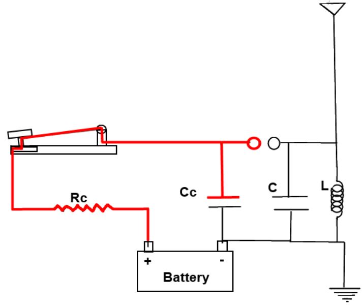
How to build a radio transmitter:
Here is a very simple spark gap radio transmitter. It is the
most basic transmitter you can create. Let's look at how it
operates.
1. When the telegraph key is depressed, it forms a complete
circuit and the electricity from the battery flows through
resistor Rc into capacitor Cc. The charge on this capacitor
starts to rise.
2. In just milliseconds, the voltage of Cc rises to a level
where current will arc across the spark gap.
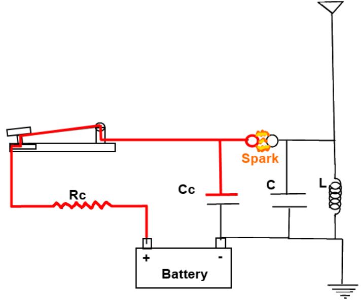
3. The spark ionizes the air forming a conducting path that
allows the charge in capacitor Cc to rush across the gap into
capacitor C.

4. The coil “L” and capacitor “C” along with the resistance
“R” of the circuit make up a resonator. A resonator an
elemental electrical circuit that will "ring" or resonate at a
specific frequency when exposed to the proper electrical
impulse. This is analogous to a bell being struck with a
hammer.
5. The surging current coming across the spark gap acts as
such a hammer. It starts the LCR circuit oscillating. During
the oscillations, the voltage on the upper terminals of the
inductor and capacitor switches back and forth between
positive and negative until the oscillations are damped out by
the effects of the resistance and radiation losses.
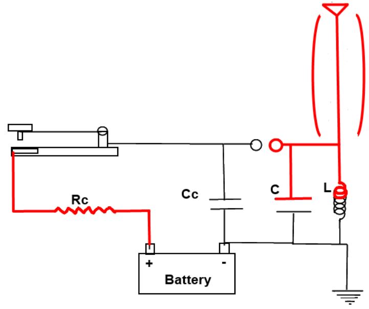
6. The voltage in the antenna is forced to oscillate at the
same frequency of the LCR circuit since it is connected to the
circuit.
7. The antenna needs to be a specific length so that a
standing wave is set up in the antenna. This is like sizing a
bell so that it will ring at a certain frequency. This
greatly increases the efficiency with which the antenna
radiates. The length of the antenna needs to be ¼, ½ or 1
wavelength of the frequency you want to broadcast. So for 600
kHz that would mean an antenna of 410ft, 820ft or 1640ft
(125m, 250m or 500m).
8. Oscillating voltage in the antenna sets up an alternating
magnetic field around the antenna. The alternating magnetic
field will in turn create an alternating electric field in
space further out from the antenna. That alternating electric
field will create another magnetic field farther out which
creates another electric field and it just keeps going on and
on. The electromagnetic wave is propagated or broadcast from
the antenna.

These primitive transmitters produced an unmodulated carrier
wave so they are limited to transmitting in Morse code. What
makes modern transmitters better? One major difference is that
modern transmitters have a much better oscillator circuits
(There are more differences but let's stop there). They don’t
broadcast on a wide band of frequencies like the spark gap
transmitter. Modern transmitter’s oscillators produce the
exact carrier frequency they want to transmit. The information
to transmit (such as voice) is overlaid on top of this carrier
frequency. If it is done by modulating the amplitude of the
carrier wave, we call it AM radio. If it is done by modulating
the frequency of the carrier wave, we call it FM Radio. I
won’t bother going into more detail than that because
transmitting Morse code wirelessly is enough to be called
reinventing radio. If you are interested in advancing to about
1929 for transmitter technology you can check out these links
to building a 1929 style TNT transmitter. This transmitter is
sufficiently modern that you could operate it today provided
that you have a license to do so.
Now that you can transmit Morse code via radio waves, you need
some way to receive it. In its essence, a radio receiver is an
LRC circuit with an antenna that can be used to detect radio
waves. Like the early transmitters, the early receivers are
very simple and they provide a nice way to talk about the
fundamentals.
Lets look at some of Marconi's technology:

A rough schematic of
Marconi's original wireless system |
A photograph of Marconi's 1895 transmitter |
A more detailed
schematic of Marconi's 1900 wireless system which
incorporates |
|


![]()
Pictorial diagram of a simple spark-gap transmitter showing examples of the early electronic components used. From a 1917 boy's book, it is typical of the low power transmitters homebuilt by thousands of amateurs to explore the exciting new technology of radio.
Wireless Telegraph
It is hard to imagine what the
modern world would look like without the constant exchange of a huge
quantity of information. It is currently disseminated by various
means such as newspapers, telephone and the Internet. However the
fastest way, and sometimes the only way, is by radio. This is where
the transfer is by electromagnetic waves, traveling at the speed of
light. In radio communication, a radio transmitter comprises one
side of the link and a radio receiver on the other. No conductor of
any kind is needed between them, and that's how the expression
Wireless Link came into being.
In the early days of radio engineering the terms Wireless
Telegraph and Wireless Telephone were also used, but were
quickly replaced with Radio Communication, or just Radio.
![]()
Radio communication is created by
means of electromagnetic waves, of which the existence and features
were theoretically described and predicted by James Maxwell, in
1864.
First experimental proof of this theory was given by Heinrich Hertz
in 1888, ten years after Maxwell's death.
It was already known at that time that electric current exists in
oscillatory circuits made of a capacitor of capacity C and
coil of inductance L. It was Thomson, back in 1853 that
determined the frequency of this arrangement to be:
![]()
Hertz used an oscillatory circuit with
a capacitor made of two bowls, K1 and K2 (Pic. 1.1), and the "coil"
was made of two straight conductors. The bowls could be moved along
the conductors. In this way the capacitance of the circuit could be
altered, and also its resonance frequency. With every interruption
from the battery, a high voltage was produced at the output of the
inductor, creating a spark between the narrow placed balls k1 and
k2. According to Maxwell's theory, as long as there was a spark,
i.e. alternating current in the circuitry, there was an
electromagnetic field surrounding the conductors, spreading itself
through the surrounding space. A few metres away from this device
Hertz placed a bent conductor with metal balls k3, k4 placed on the
ends, positioned very close to each other.
This also was an oscillatory circuit, called the resonator.
According to Maxwell's theory, voltage induced by the
electromagnetic waves should be created in the resonator. Voltage
existence would be shown by a spark between the balls k3 and k4.
And that's the way it was: Whenever there was a spark in the
oscillator between the balls k1 and k2, a spark would also be
produced by the resonator, between balls k3 and k4.
With various forms of the arrangement in Pic. 1.1, Hertz proved that
electromagnetic waves behave as light since they could also be
reflected and refracted.
It was also shown that light is of electromagnetic nature, as stated
by Maxwell.
Hertz, however, did not believe in the practical value of his
electromagnetic waves experiments. The range of the link was no
further than a few meters. The transmitted signal was very weak,
therefore the signal in the receiver had a very small amplitude and
it wasn't possible to detect it at a greater distance. The
possibility of amplifying the signal in the receiver did not exist
at the time.
Besides the short range, another shortcoming of the link was noted:
If another similar transmitter was working nearby, a receiver
detected all the signals at the same time. It did not have the
ability of isolation.
However crude and simple these experiments were at the time, they
represented the birth of a new scientific branch - Radio
Engineering.
The pioneers of radio were Popov and Marconi, but the place of honor
belongs to Nikola Tesla, who demonstrated wireless broadcasting in
1893, at the Franklin Institute.
Pic.1.2 shows the arrangement of this broadcast system.
Tesla's idea was to produce electromagnetic waves by means of
oscillatory circuits and transmit them over an antenna. A receiver
would then receive the waves with another antenna and oscillatory
circuit being in resonance with the oscillatory circuit of the
transmitter. This represented the groundwork of today's radio
communications.
In 1904 John Flemming created the diode, and in 1907 Lee De Forest
invented the triode. That year can be considered the birth of
electronics, with the triode being the first electronic component
used in a circuit for signal amplification.

Rapid development of radio engineering
over the ensuing years produced many innovations and after the First
World War a huge number of radio stations emerged.
At that time TRF (Tuned Radio Frequency) receivers were used.
Compared to modern receivers they had both poor selectivity and
sensitivity, but back then they fulfilled the demands. The number of
radio stations was much less than today and their transmitting power
was much smaller. The majority of listeners were satisfied with the
reception of only local stations. However as the number of stations
increased, as well as their transmitting power, the problem of
selecting one station out of the jumble of stations, was becoming
increasingly more difficult.
It was partially solved with an increase in the number of
oscillatory circuits in the receiver and the introduction of
positive feedback, but the true solution was the invention of the
superheterodyne receiver. This was accomplished by Lewy (1917),
and improved by E.H. Armstrong (1918).
An enormous impact on the world of radio was the invention of the
transistor by Bardeen, Bretten & Schockley, in 1948. This reduced
the size of the radio receiver and made truly portable sets a
reality.
This was followed by the introduction of the integrated circuit,
enabling the construction of devices that not only proved better in
every way than those using values, but also new designs.
Radio amateurs' contribution to radio engineering should also be
emphasized.
In the beginning, radio communication was being conducted in the LW
and MW bands. But achieving long-distance reception required very
powerful transmitters. The SW band was considered to be useless for
radio broadcast on long distances and was given to radio amateurs.
The were banned from using LW and MW bands by commercial radio
stations.
However, something unexpected happened: Amateurs were able to
accomplish extremely long distance transmissions (thousands of
kilometres), by using very low-power transmitters. This was later
explained by the influence of the ionosphere layer, the existence of
which was also predicted by Tesla.
Modern radio receivers differ greatly from the "classical" types,
however the working principles are the same.
The only significant difference is in the way the receiver is tuned to a station. Classical devices used a variable capacitor, coil or varicap diode, with the frequency read from a scale with movable pointer. In modern devices, the adjustment is done with a frequency synthesizer controlled by a microprocessor and the reading is displayed on an optical readout.

The figure below shows an arrangement
for generating a traveling electromagnetic wave in the shortwave
radio region of the spectrum: an LC oscillator produces a sinusoidal
current in the antenna, which generates the wave. What is the
wavelength of the wave emitted by this system if L = 0.283 H
and C = 35.0 pF?

The inclusion of a microprocessor enables any one of a large number of pre-tuned stations to be selected and displayed and the use of a remote control makes the receiver even more user friendly.


The apparatus used by Hertz in 1887 to generate and detect electromagnetic
waves. An RLC circuit connected to the first loop caused sparks across a gap in
the wire loop and generated electromagnetic waves. Sparks across a gap in the
second loop located across the laboratory gave evidence that the waves had been
received.


The apparatus used by Hertz to generate and detect a radio wave.


Hertz Apparatus
![]()
A schematic diagram of a basic spark transmitter.
The high voltage secondary of the induction coil is connected to a condenser, which is a Leyden jar or a heavy glass plate condenser, which feeds the spark gap and the primary of the oscillation coil. The condenser and the oscillation coil primary form the tuned tank circuit, which establishes the transmitter frequency. The oscillation coil secondary is connected to the transmitting antenna and to ground, and is also tuned to the same resonant frequency as determined by the oscillation coil secondary inductance and the capacitance of the antenna. The transmitted power is determined by the length of the arc which could be developed across the gap; the longer the spark the more power transmitted.
Simple Morse Code Transmitter:
That picture is an intersting application of the simplest broadcast transmitter
called Galena. Requires few amount of electronic components. Repair that no
intermediate frequency is used.
However this kind of transmitter takes a wide band of RF spectrum and may be
considered just for emergency purposes. At normal operation you should work
under hiperheterodine topology circuit.
If you intend operate this equipment need perform a survey at your country
regulations regarding what are the free use radio frequency spectrum ranges.
Answering your question : The receiver you can build also simply like
bellow :


Bobin(L) ve Kondansatör (C) devresi BİR REZONANS DEVRESİ olarak adlandırılmaktadır. Buna basitçe bir osilatör devresi deniyor. Kondansatörün değerine ve bobinin sarım sayısına, çapına, iletken kalınlığına bağlı olarak devrenin salınım frekansı belirleniyor. Bu elektromanyetik bir salınım üreten devredir. Bobinden bir anten çıkartılabilir. Antenden sinyaller yayılır. Alıcı ve verici sistemlerde temel prensipte aynı osilatör devreleri kullanılır. Bu devrelerin birisi dalga üretecidir. Diğer alıcı osilatörde vericinin rezonans frekanslarına kendini ayarlayarak çok zayıf akımlar oluşturarak aynı şekilde tireşir.. bu elektrik sinyalleri (oslatör salınımı) alıcıda transistörler yardımı ile güçlendirilerek hoparlöre yada bir tür mors alfabesini alan elektromıknatısa verilerek bu sayede ses yada mors kodlaması alınabilir. Aslında alıcıdaki hoparlör vericideki yayın frekansını etkileyen (değiştiren/kodlayan/fm modülasyon) anahtarlama sisteminin (yada mikrofonun) bir benzeridir. Basit bir radyo vericisinde sistemin yani L ve C elemanlarının bir salınım frekansı var. Mikron sayesinde yada bir tür anahtarlama palsleri sayesinde bir fm modülasyon (sinyal frekansı değişimleri) yapılmaktadır. Telsiz telgraftaki elle basılıp çekilen anahtar sistemide bir çeşit sinyal kodalayıcı mikrofon vazifesi görevi görmektedir. Ses sinyalleri yerine aralıklı darbeler/vuruşları karşı tarafa göndermektedir. Elektomanyetik dalgaların genliğine (am) yada frekansına (fm) etki edecek şekilde mikrofon sistemini osilatör sistemine dahil ediyoruz. Osilatör devresi ile birleştiriyoruz. Sonuçta alıcadada vericidede benzer bir osilatör sistemi var. Alıcıdaki hoparlör verici sistemdeki mikrofon'a karşılık gelmektedir. Bu telsiz telgraftaki iki taratfa bulunan elektromıknatıssal anahtar sistemlerine benzetilebilir. Rezonans frekansları sayesinde alıcı osilatöre bağlı elektromıknatıs aynen verici osliatöre bağlı elektromıknatısın açılıp kapanma sekansını kopyalar (kendi içinde taklit eder). Bu durum bir bardağı titreştirirken diğer yerdeki bir başka bardağında oluşan yayılan ses dalgaları etkisi ile rezonansa gelip aynı şekilde titreşmesine benzetilebilir.
![]()
However the days of “spark gap” transmitters and “coherer” receivers are long gone, and with the advent of the radio Valve, it became possible to transmit energy on a single radio frequency, rather than as a continuous spectrum of on and off noise. This allowed the transmit energy to be concentrated into one narrow channel rather than spread out all over the show. It also allowed more sensitive receivers to be constructed, and more importantly, selectivity, or the ability to differentiate between signals on different frequencies, became possible. The first transmitters and receivers used Amplitude Modulation (AM) to convey messages, and for the first time actual voice and music communication became possible. In addition, the technology was now within the reach of the consumer, and the golden years of Broadcast radio began.
![]()
Below is a schematic diagram of Hertz's transmitter. You can see that he used a Ruhmkorff coil to induce a huge voltage across the spark-gap in the antenna.
![]()
You see, below, the setup for detecting Hertzian waves.
![]()
The graph shown in the figure below shows the relationship between the magnetic (H) field and the electric (E) field plotted against time. Note that the two fields are 90 degrees out of phase with each other in time. It is also true that the two fields around the antenna are displaced 90 degrees from each other in space. The H field exists in a plane perpendicular to the antenna. Its field lines circle the axis of the antenna. The E field exists in a plane parallel with the antenna. Its field lines arc along the length of the antenna.

Electromagnetic Waves
Heinrich Hertz (1857-1894), a German science student, was encouraged by his
teacher, Hermann Helmholtz, to pursue his explorations of electromagnetism.
While it had been known for some time that electric current produces magnetism,
in 1887 Hertz demonstrated that magnetism travels through the air in the form of
electromagnetic waves, thus providing concrete evidence of Maxwell's equations.
Hertz sent a spark between two charged rods. Across the room, another spark was
induced between two charged rods, demonstrating that electrical current causes
electromagnetic waves to propagate, which in turn can induce electrical current
elsewhere.


Hertz carried out his experiment with an oscillator, a variation on the spark
gap transmitter. Once again, the two plates of a battery are connected to the
oppositely charged plates of a capacitor. With the plates farther apart and
without the secondary coil, there is much less capacitance in the plates,
causing the frequency of the oscillations between the plates to be much higher
since electrons didn't have time to collect in either plate. Modifications to
this basic design allowed the distance between the capacitor plates to be
adjusted, which allowed the frequency of its oscillation to be changed. With the
plates separated and with the absence of the magnetic field from the secondary
coil, the electromagnetic waves from the sparks were not "muffled" and thus had
a greater tendency to travel away from the spark gaps.

In a crude form, Hertz's demonstration of electromagnetic waves transmission
constituted the first radio broadcast.

A spark-gap radio transmitter
![]() Figure : r
Figure : r
Figure r shows a primitive type of radio transmitter, called a spark gap
transmitter, used to send Morse code around the turn of the twentieth century.
The high voltage source, V, is typically about 10,000 volts. When the telegraph
switch, S, is closed, the RC circuit on the left starts charging up. An
increasing voltage difference develops between the electrodes of the spark gap,
G. When this voltage difference gets large enough, the electric field in the air
between the electrodes causes a spark, partially discharging the RC circuit, but
charging the LC circuit on the right. The LC circuit then oscillates at its
resonant frequency (typically about 1 MHz), but the energy of these oscillations
is rapidly radiated away by the antenna, A, which sends out radio waves.
In his experiments, Hertz first employed a pair of one meter wires with a spark
gap in the center connected to an induction coil. The large spheres at the ends
were used to adjust the capacity of the circuit for resonance.

At Karlsruhe in Berlin, Hertz conducted his landmark experiments in radio
transmission. After countless preliminary experiments, Hertz constructed a
high-voltage transmitter circuit that included two metal spheres separated by I
to 2 cm. They were positioned at the focal point of a large metal parabolic
mirror. Electrical power came from o bank of wet cell batteries and an induction
coil 52 cm high by 20 cm in diameter. Relay contacts provided the make-and-break
cycle to generate high voltage from the coil. The rapidly oscillating ac current
produced sparks that jumped the gap between the metal spheres. His receiver was
a 70 cm diameter loop of wire with smaller metal spheres separated by about 3 mm
at the ends. It was a forerunner of the dipole antenna. Hertz placed the
receiver at different parts of a darkened room, typically 20 meters from the
transmitter. High-voltage sparking at the transmitter induced weak sparks to
jump the gap at the receiver. With this oscillator, Hertz solved two problems.
First, he was timing Maxwell's waves;he had demonstrated, in the concrete, what
Maxwell had only theorized that the velocity of radio waves was equal to the
velocity of light. Second, he solved how to make the electric and magnetic
fields detach themselves from wires and go free as Maxwell's waves.
In 1886, Hertz sent and received energy through space, something never done
before. He conducted a series of complex experiments showing that electrical
signals were energy waves, just like light. He focused the waves with different
devices and calculated their lengths. He developed efficient antennas and
discovered that short waves are better for information transmission than longer
ones, thus establishing the foundation for modern electronic communication. His
work resulted in the first long-distance radio communication with Hertzian
waves, as they were called.
His name is now given to the unit of frequency - one cycle per second - (Hertz)
and is abbreviated Hz. This replaced the use of cycles per second for the unit
of frequency in the late 1960's.
Genel Kültür ve İcatlar Ansiklopedisinde sizlereTelgraf Nedir
Kısaca Telgrafın İcadı ve Tarihçesi Hakkında Bilgi
Telgraf, iki merkez arasında, kararlaştırılmış işaretlerin yardımıyla yazılı
haberlerin veya vesikaların mesaj ile iletilmesini sağlayan bir telekomünikasyon
düzenidir.
Elektrikli telgraflar, bir verici, bir alıcı ve ikisi arasına çekilmiş elektrik
hattından alana gelir. Vericiye maniple denir. Maniple, telgraf ağındaki
elektrik akımını açıp kapayan anahtarlardır. Manipleye basınca devre bitirir ve
telgraf ağından akım geçer.
soru-cevaplar
Karşı tarafta ise alıcılar vardır. Alıcılar, elektro mıknatıs makaralardan
yapılmışlardır. Elektro mıknatısın karşısında ileri geri hareket edebilen madeni
bir çubuk vardır. Bu çubuk elektro mıknatıstan akım geçtiği vakit hareket eder.
Çubuğun ucundaki mürekkepli kalem bir kâğıt şerit üzerine nokta (.) veya çizgi
(–) şeklinde şekiller çizer.
Sesle çalışan alıcılar da vardır. Bunlar kâğıt bir şeride yazı yazmak yerine,
sert bir cisme vurarak tıkırtı çıkarırlar. Deneyimli telgraf operatörleri, bu
tıkırtıları dinleyerek iletisi çözerler. Burada kısa tıkırtı nokta (.), uzun
tıkırtı çizgi (–) manasına gelmektedir.
Claude Chappe, 1792 senesinde telgraf isminde bir sistem ortaya attı. Tepelerin
üzerine heyetmiş kulelerden bir ağ oluşturuldu ve her kulenin üzerinde 49
değişik konuma ayarlanabilen iki uzun kola sahip bir makine vardı. Her konum bir
harfe veya bir rakama karşılık geliyordu. Bu sistem çok başarılı oldu. 19. asrın
ortalarında Fransa’daki kule ağı takriben olarak 4828 kilometreydi.
1830 senesinde AMERİKA BİRLEŞİK DEVLETLERİ’li Joseph Henry (1797-1878), elektrik
akımını teller aracılığıyla uzaklara taşıyıp, oradaki bir zili çalıştırdı. Zil
bir elektromıknatısa bağlıydı. Bu elektrikli telgrafın doğuşuydu.
1832 senesinde AMERİKA BİRLEŞİK DEVLETLERİ’li ressam Samuel Morse, bir yolculuk
esnasında kendisine elektro mıknatıstan söz eden bir yolcuyla tanışmıştı.
Telgraf üstünde zati çalışmaları olan Morse, bu sefer elektro mıknatıslı telgraf
için çalışmaya başladı.
1835 seneninde,Samuel Morse ilk elektromıknatıslı telgrafını yaptı. O telgrafta
bulunan elektromıknatısa başlı bir kalem vardı. Bu kalem kâğıt bir şerit üzerine
elektro mıknatıstan aldığı hareketle zig zag çizgiler çiziyordu. Bu sistem pek
başarılı değildi.
Daha sonra Morse ve yardımcısı Vail bunu geliştirdiler. Nokta ve çizgilerden
oluşan bir kodlama sistemi ortaya çıkardılar. Bu kodlama sistemi, daha sonra tüm
dünyada kabul gören Mors alfabesiydi
O senelerde telgraf en popüler iletişim aracı oldu. İlk telgraf hattı ise 1843
senesinde Washington, D.C. ile Baltimore, Maryland arasına çekildi.
Telefonun İcadı (Alexander Graham BELL)
XIX. yüzyılın son çeyreğinde Morse telgrafı standart araçları, kuralları ve
uzmanlarıyla tam örgütlenmiş bir kamu hizmeti durumuna gelmişti. Ve sayısız
araştırmacılar daha da geliştirmek için harıl harıl çalışmaktaydılar. Çabaları
özellikle iki yön izlemekteydi: En kısa zamanda masrafları karşılayacak azami
hızı ulaşımda sağlamak; bir de Morse alfabesini bir yana bırakıp mesajları
normal yazıyla alabilmek…
Birincisini duplex (çift taraflı haberleşme) tekniğiyle yani her iki yönden
birden mesaj göndermek yoluyla sağladılar. Bu güzel icat iki kişinin eseri oldu:
Wheatstone (1852) ve Amerikalı Stearns (1868). Ünlü Thomas Edison da bunu
1871′de guadruplex sistem haline soktu.
İkinci sorun için ilk çözüm bulan İngiliz Davit Hughes (1831-1900) oldu.1855′te
alfabenin harflerine karşılık olan bir klavye teklif etti. Ama yine de en köklü
çözüm yolunu basit bir telgraf teknisyeni olan Fransız Emile Baudot (1845-1903)
gösterdi. 1874′te karma bir yol Hughes ile şirketinin kullandığı Morse
makinelerinin birleştirilmesini teklif etti. Ve bunu gerçekleştirmeyi başardı.
Böylece yazılı bir telgraf meydana getirmekle kalmadı, birkaç mesajı (5-6 taneyi)
birden gönderme imkânını da sağlamış oldu.
Açıkgöz bir adam olan Baudot, icadının beratını almaya ve makinesini P.T.T.’ye
kabul ettirmeyi başardı. Bunun kendisine paraca bir tatmin sağladığı
söylenemezse de adının Morse’unki gibi gelecek kuşaklara bir cins isim olarak
kaldığını görmek kıvancına erişti.
Telefon Baudot’nun ilk denenmesi sırasında icat edildi.
Bu icadın da uzun bir geçmişi olmuştur. İlkini, sicimi: telefonu (Hooke) bir
yana bırakalım; 1782′de sesleri 800 m. uzağa götürmeyi deneyen Papaz Dom
Gauthey’i de anıp geçtikten sonra, bu alanda ciddi ilk çalışmayı yapmış olan
Amerikalı Charles Page’a (1812-1873) gelelim. Page yumuşak demir parçacıklarını
hızla mıknatıslamak ve mıknatıslığını gidermek yoluyla sesleri almayı başarmıştı.
Meslektaşı Cenevreli fizikçi Auguste de la Rive (1801-1873) bunu geliştirdi ve
işi, telefonun gerçek ön-icatçısı olarak sayacağımız Alman fizikçi Philipp Reiss
(1801-1873) ele aldı .

Reiss makinesi sesin titrediği bir zardı ve bu titremeler elektrik devresini
kapatmaktaydı.
Reiss, uluslararası üne sahip bir bilgin değildi. Öyle ki, çalışmaları kendini
aynı çalışmalara vermiş olan Amerikalı profesörün kulağına rastlantıyla çalındı.
Bu bir diksiyon profesörünün oğlu olup 3 Mart 1847′de Edinburg’da doğan Graham
Bell idi. Kendisi de babası gibi fonetikle konuşma mekanizması ve sağır
dilsizlerle ilgilenmişti. Bu alandaki incelemeleri sırasında Holmholtz’un
“İşitme Duyusu Açısından Müziğin Fizyolojik Teorisi” (1863) adlı eserinden,
elektromıknatısın etkilediği bir diyapazon aracılığıyla nasıl sesler elde
edilebileceği hakkında fikir edinmiş ve elektrik konusunda incelemeler yapmaya
başlamıştı.
1872′de A.B.D.’ye göç eden ve Boston Üniversitesine ses fizyolojisi profesörü
olarak atanan Bell, sağırlarla ilgili projelerini bir yana atmış değildi; hatta
bir sağır kadınla evlenmişti. O kadar ki, 1875′te bir telgraf maniplesi
aracılığıyla bir diyapazonu onlar için titreştirmişti. Günün birinde diyapazonun
yerine mıknatıslı maden parçaları kullandı ve bunlardan birinin kuru bir ses
çıkararak elektromıknatısa gidip yapıştığını gözlemledi. Ani bir esinlemeyle
irkildi. Maden parçacıklarının yerine bir zar yerleştirdi ve zarı titreşimlerine
göre direnci değişen bir elektrik devresine bağladı. Sonra telin öbür ucunda
çalışmakta olan asistanına seslendi: “Bay Watson, gelin! size ihtiyacım var.”
Watson şaşkın ve ürkek bir tavırla koşup geldi: Patronunun sesini telefondan
duymuştu.
Bu olay 10 Mart 1876′da olmuştu. O zamanlar ilim adamları bu icadı Amerika’nın
en olağanüstü buluşu olarak nitelemekteydiler, ama o haliyle çok olduğu da bir
gerçekti. Bir elektrik jeneratörüyle çalışmıyordu. Elektrik akımını yaratan,
vericideki manyetik alanın değişimleriydi ve bu telden geçerek alıcıdaki
elektromıknatısı harekete getiriyordu. Bu durumda 10-12 metreyi aşamazdı. Aygıtı
ilk geliştiren Edison oldu (1876). Vericiye bir pil bağlayarak gücünü artırdı.
1878′ de Hugnes mikrofon’u icat etti ve böylece zarların titreşimleri sonucu
elde edilen sesleri büyük oranda yükseltmek mümkün oldu.
Böylesine olağanüstü bir buluş, sözgelişi, New York’ta iken Boston’daki
arkadaşının sesini duymak görülmemiş bir heyecan yarattı; olaylara,
kıskançlıklara, kinlere ve davalara konu oldu. ilk davayı açan Amerikalı değerli
teknisyen Elisha Gray (1835-1901) idi. içine kapanık bir araştırmacı olan Gray
telefonu Graham Bell’le aynı zamanda bulmuş, ama ne yazık ki beratını ondan iki
saat sonra istemişti. Bu 120 dakikalık gecikme mahkemelerin, haklarını
reddetmesi için yetti. Graham Bell’in, icadını telgraf şirketi Western Union’a
teklif edip (1877) reddedilmesinden sonra kurulan Bell Telephone Şirketi
aleyhine; sözde başka mucitler, geliştiriciler ve rakipler tarafından bir yığın
davalar açılmaya başlanmış, bir yandan da berat meseleleri çevresinde tatsız
didişmeler ve açgözlü çekişmeler almış yürümüştü.
Bütün davalar art arda gerçek mucidin lehine sona ermekteydi. Telefon da bir
yandan durmadan yayılmakta, teller şehirlerden şehirlere uzanmaktaydı. 1880
yılında Amerika’nın 35 eyaleti telefon santralına kavuşmuş ve 70.000 abone
kaydetmişti. Bell 4 Ağustos 1922′de Halifax’da öldüğünde A.B.D. ve Kanada’daki
17 milyon abonelik şebekede ulaşım bir dakika durduruldu.
1876′da telefonun icadı bunca hayranlık dolu bir şaşkınlık yarattıktan sonra
fonografın etkisi ne oldu, bir gözünüzün önüne getirin. Oysa bu konu da ani
olarak patlak vermemiş, çalışmalar az çok kulaktan kulağa duyulmuştu. Bilim
adamları uzunca bir süreden beri uğraşmaktaydılar; hatta 1857′de yarı yola
varmışlardı bile. O yıl mütevazı bir basın musahhihi olan Fransız Edouard-Leon
Scott (1817-1879), gerçek bir kaydedici fonograf imal etti. Bu, altında bir
silindirin döndüğü madeni bir sivri uç ve buna bağlı bir zardan oluşmuştu. Bu
zarın önünde konuşulunca ya da şarkı söylenince sesler sivri madeni uç
aracılığıyla silindirin üzerinde titreşimli izlet bırakıyordu.
Bu kaydetmenin tersinin olabileceği yani sivri ucu bu izlerden bir daha geçirmek
yoluyla söz ya da müziği yeniden meydana getirmek bambaşka bir alandı elbet. Ve
kolay kolay kimsenin aklına gelecek şey de değildi. Bunu ilk düşünen Charles
Cros (1842-1888) adında bir Fransız oldu. Cros şair, mizahçı, hem de bilim
adamıydı. Bir yandan şiirler yazıyor, bir yandan da teorik olarak renkli
fotoğraf, gezegenlerarası ulaşım ve fonograf tasarlıyordu. Tasarıları
gerçekleşti ve 1877′de Bilimler Akademisine, “paleophone” adını verdiği gerçekte
bir fonograf olan bir aletin planını sundu.
Edison’un bu çalışmadan haberi oldu mu? Yoksa yalnızca bir rastlantı sonucu
olarak mı bilmiyoruz; tıpatıp aynı ilkelere dayanan makinesi için berat istedi.
Edison’u bu makinenin önünde çocukça bir şarkı olan “Mary had a little lamb -Mary’nin
minik bir kuzusu var” şarkısını söylerken görenler, makinenin az sonra hımhım
bir sesle bunu tekrarladığını duydular.
1878′in fonografı bir oyuncaktı, ama inanılmaz bir gelişme gösterdi ve günümüzün
elektrofon ve mikrosiyon plaklarına bir yığın yeni buluş ve icatlara yol açtı…
Telefon nasıl çalışır?
Bir elektrik devresi üzerinden bir telefon konuşmasının yapılması
sırasında meydana gelen olaylar şöylece sıralanabilir:
1. Ses enerjisi mekanik enerjiye dönüşür.
2. Mekanik enerji elektrik enerjisine dönüşür.
3. Elektrik enerjisi nakledilir.
4. Karşı tarafta elektrik enerjisi manyetik enerjiye dönüşür.
5. Manyetik enerji mekanik enerjiye dönüşür.
6. Mekanik enerji ses enerjisine dönüşür.
Elektrik titreşimlerinin iletkenlerdeki yayılma hızı esas titreşimlerinin
havadaki yayılma hızından birkaç yüz bin kere daha fazla olduğundan (200-300 bin
km/sn mertebesinde) telefon ile konuşanlar, aradaki uzaklığa rağmen, karşı
karşıya bulunuyorlarmış hissine sahiptirler. Telefon sistemi üç ana görev yapar.
İki abone arasında konuşma irtibatını sağlar ve aboneler arasında çağırma,
meşgul çevirme, ses sinyalleri üretir. Otomatik olmayan manyetolu telefonlarda
bu işlemler elle yapılır.
Bir telefon aletinde bulunan belli başlı parçalar şunlardır:
1. Ses alıcı (mikrofon),
2. Mikrofon akım kaynağı,
3. Ses verici (kulaklık),
4. Çağırma ve çağrılma düzenleri,
5. Devre açıp kapayıcılar, anahtarlar,
6. Çağırma kadranı.
Manuel ve otomatik santrallara bağlı telefon aletleri birbirinden farklıdır.
Herbirinde yukardaki parçaların bazıları bulunur. Telefonun ahizesi sesi
elektrik enerjisine ve elektrik enerjisini de sese çevirir. Otomatik telefon
cihazında ahize kaldırıldığında devreyi açan bir anahtar ve ön tarafta
numaratörü mevcuttur. Telefon ahizesi kaldırılınca telefonla santral arasında
elektrik devresi kurulur. Ahizeden ton sesi duyulur. Numaratörden, mesela 6
rakamı çevrilince elektrik devresi altı defa açılıp kapanmış olur. Elektrik
devresindeki açılıp kapanmalar sinyal olarak santralda devreler vasıtasıyle
sayılır.
Muhaberenin konuşma şeklinde olması şart değildir. Lokal santrallara konulan
bilgisayarlar gönderilen sinyal cinsine göre seçim yaparak dağıtımı analog
telefon, sayısal telefon, faksimile, teleks, televizyon bilgi işlem şekillerinde
terminallere ulaştırır. Böylece telefon konuşmaları yanında televizyon, faksimil
resim ve yazı, teleks, bilgisayar işlemleri de çok süratli ve kaliteli olarak
yürütülür.
Muhabere hatları: Muhabere (haberleşme) imkanları çok çeşitlidir. Bunlar:
1. İki telli analog radyo sinyal hattı (1 konuşma).
2. Anolog radyo röle link hattı (30 konuşma).
3. Sayısal radyo röle link hattı (1920 konuşma).
4. Çok kollu koaksiyel kablo hattı (7680 konuşma).
5. Fiberoptik kablo hattı (10.000 konuşma ve üstü).
6. Muhabere uydular hattı (20.000 konuşma).
İki telli konuşma devreleri uzak mesafelerde kayıplar çok arttığı ve kanal
sayısı sınırlı olduğu için şehir içi dağıtım sistemi dışında kullanılmaz.
Muhabere sistemleri radyo yayınlarından istifadeyle kapasite ve kalite yönünden
çok gelişmiştir. Telefon konuşmaları hem doğrudan analog sinyal olarak hem de bu
analog sinyalin sayısal sinyal haline çevrilmesinden sonra yayınlanarak
yapılabilmektedir. Analog sinyal de yankı problemi ve sinyal gürültü seviyesi
yüksek olduğu için terk edilmiş sayısal sinyal sistemine geçilmiştir.
Sayısal sinyal sistemlerinde, analog sinyal dilimlere bölünerek düzgün palslara
ayrılır. Bu palslar daha sonra kodlanarak verici anteninden ‘0′, ‘1′ sayısal
yayın olarak gönderilir. Kodlanma işlemi her konuşma için ayrı ayrı
yapılabildiği için bir antenden aynı anda binlerce sayıda konuşma palslar
halinde yayınlanabilir. Alıcı telefon, istasyondan alınan bu binlerce yayın
tekrar kod çözücüde çözümlenerek, odyo sinyal haline çevrilerek santral mantık
devresinden geçerek abonelere ulaşır. Kodlanmış palslar antenden
yayınlanabildiği gibi koaksiyel kablolardan da gönderilebilir. Koaksiyel
kablolarda kayıplar çok azalır. Koaksiyel kablo yerine bundan daha süratli
yüksek kapasiteli ve kayıp oranı çok düşük optik fiber kablolar da
kullanılabilir. Optik fiber sisteminde kodlanmış sayısal sinyaller optik
sinyallere çevrilerek gönderilir. Karşı santralde optik sinyaller önce
elektronik sinyallere daha sonra da odyo analog sinyale çevrilerek lokal santral
mantık devresinden abonelere ulaştırılır.
İki telli muhabere sisteminde aynı anda bir konuşma yapılır. Halbuki pals kod
modüleli sayısal radyo link muhabere sisteminde 30 kanal mevcuttur. Koaks
kablolu sayısal radyo link muhabere sistemiyse en az saniyede 30 megabit bilgi
gönderme kapasitesine sahip olup, 1920 kanallıdır. 1985 senesinde F. Almanya’da
hizmete girmiş olan böyle bir sistem saniyede 565 mbit kapasiteye; bir başka
ifadeyle aynı anda 7680 konuşma veya bilgi aktarmaya müsaittir. Fiberoptik
sistemler 140 mbit/saniye ve daha yukarı kapasitede görev yapmaktadır.
Fiberoptik muhabere sistemi kapasite yüksekliği, montaj kolaylığı, bakım
istememesi, yüksek kaliteli bilgi göndermesiyle mevcut sistemlerin en
mükemmelidir.
Özet olarak telefon santrallarının isimleri şunlardır: Elektromekanik telefon
santralı, elektronik telefon santralı, otomatik telefon santralı, şehirlerarası
telefon santralı, transit telefon santralı, yarıelektronik telefon santralı,
yarıotomatik telefon santralı, mahalli (yerel) telefon santralı… olmak üzere
çeşitleri vardır (1994).
Telefonun tatbikatta sağladığı en büyük fayda muhaberenin süratli bir şekilde
yapılmasıdır. Fiberoptik, koaksiyel kablo ve elektromanyetik yollarla uydulardan
yansıtılarak yapılan telefon görüşmeleri dünyanın her köşesini birbirine
bağlamıştır. Telefon sistemlerinin kanal kapasiteleri her geçen gün artmaktadır.
Kanal sayısında artışlar telefonu daha da pratik bir hale sokmaktadır.
Telekomünikasyon arasındaki önemli gelişmelerden biri de, telsiz telefonun
ortaya çıkmasıdır. Kısa dalga radyo alıcı-vericilerin normal telefon sistemine
bağlamasıyla hareket halinde telefonla konuşma imkanı ortaya çıkmıştır. Bu
sistemle bölgeler arası kesintisiz bağlantı olduğu gibi, çok uzun menzilli
yolculuklar yapan bile istediği yeri anında arayabilir.
Telefonun Tarihi-İcadı
Yüzyıllar boyunca insanlar uzak yerlerle haberleşmeyi sağlayacak işaretler
gönderme yollarını aradılar. Mesaj iletmek için başvurulan ilk yöntemler, açık
havada yakılan ateşler ve parlayan aynalardı. Fransız Claude Chappe 1793'te icat
ettiği mesaj iletme makinesine, "uzaktan yazan" anlamında "telgraf" adını verdi.
Bu aygıtın işleyişi, kule tepesine takılmış hareketli kolların kullanılmasıyla
oluşturulan işaretler yardımıyla rakam ve harfleri iletmeye dayanıyordu.
Sonraki 40 yıl içinde elektrikli telgraf geliştirildi ve 1876'da Alexander
Graham Bell, ilk kez konuşmaları teller aracılığıyla iletmeyi sağlayan telefonu
icat etti. Sağırlarla ilgili çalışmaları, Bell'i seslerin havadaki titreşimlerle
nasıl oluştuğunu merak etmeye yöneltmiş, "armonik telgraf" adı verilen bir
düzenek üstünde çalışırken, elektrik akımının konuşma
sırasında oluşan titreşimleri andıracak biçimde değiştirilebileceğini bulmuştu.
Telefonla ilgili çalışmalarının dayandığı ilke de buydu.
Türkiye'de ilk telefon 1908 senesinde uygulanmaya başlandı. Kadıköy ve Beyoğlu
santralleri 1911 senesinde hizmete açıldı. İlk otomatik telefon santralı 1926
senesinde Ankara'da kuruldu. Ardından diğer il merkezlerinde de telefon
santralları kurulmaya başlandı.
CW Signals (continuous wave)
A fundamental and time-honoured way to transmit information is to turn the
transmitter on and off. This can be done by a Morse key (a switch). With the key
down, the transmitter is on, with the key up the transmitter is off. The dits
and dahs (the dots and dashes) of the Morse code can be sent by careful
manipulation of the key. Morse code


The term CW comes from the constant-amplitude signal transmitted with the key
down, compared to damped waves - waves which changed in amplitude - as generated
by spark-transmitters in the early days of radio communication and now totally
obselete. The term CW can be considered as synonymous with Morse code
transmission.


The "Atlantic" Wireless Telegraphy Outfit 2-part device, each unit mounted on
wooden base, with
![]()
![]()
The "Atlantic" Wireless Telegraphy Outfit
2-part device, each unit mounted on wooden base, with lockable covers. 1) Spark
transmitter, with battery, condenser, induction coil, Morse key, spark gap and
aerial. – And: 2) Receiver, with bell relay, self-tapping coherer, battery and
aerial. Designed for connection to a Morse printer. – An excellent copy, with
application as a physical demonstration or exhibition model.
HOW TO BUILD A SIMPLE WIRELESS TELEGRAPH
SET
BACKGROUND AND HISTORY OF TELEGRAPH AND
WIRELESS TELEGRAPH:
Ever since the beginnings of time, people have been trying to communicate over distances greater than the human voice could reach. Early attempts included the use of smoke signals, signal fires, waving flags, and the moving arms of semaphores. Mirrors were also used to flash the image of the sun to distant observers.
After the discovery of electricity, wires
were stretched from one point to another and an
electric current was either allowed to flow
through the wires or broken by a switch called a
telegraph key. The electric current was first
used to make marks on a paper tape and later, it
was used activate a "sounder" which made
clicking sounds. The short and long times
between the clicks could be decoded into letters
from the alphabet. This type of telegraph was
called land-line telegraph because the wires
crossed the land and used the ground as part of
the electric circuit.
This revolutionary discovery allowed people
to communicate instantly over distances that had
required days or weeks for horse or
train-carried messages. Telegraph stations were
set up along railroads first because the
right-of-way had already been cleared and it was
easy to set up poles to carry the telegraph
wires. Railroad dispatchers sent messages via
telegraph to control the movement of trains and
the wires also began to carry messages telling
of news events and business transactions. It has
been said that the "electric telegraph" was the
most significant invention of the 19th century.
At the very end of the 19th century, it became
possible to communicate by telegraph without
using wires. This 'wireless' telegraph system
paved the way for all of today's complex
wireless communications systems.
HOW WIRELESS TELEGRAPH WORKS:
Near the end of the 19th century, it was
discovered that an electric spark sent out
electrical energy which travelled through the
air without wires and could be detected at a
distant point. This discovery made it possible
to communicate without wires.
HOW TO BUILD A SIMPLE WIRELESS TELEGRAPH
SET:
The simplest wireless telegraph set consists
of a means of generating and controlling a spark
which sends out radio waves into the air. This
is called a transmitter. A complete wireless
telegraph set also requires a receiver or
detector to detect the radio waves.
HOW TO BUILD A SIMPLE WIRELESS TELEGRAPH
TRANSMITTER:
Probably the simplest way to generate and
control a spark is to use a switch (called a
telegraph key) to turn on and off an
electromagnetic buzzer which generates sparks.
The simplest way to receive or detect the radio
waves generated by the buzzer is to use an AM
radio tuned to a place on the dial where there
are no other stations.
Here is the simple wireless transmitter which is basically an electrical circuit consisting of 3 parts, all hooked together by wires.
A BATTERY supplies the electricity or
voltage.
A KEY is used to complete or break the circuit.
A BUZZER is used to generate the sparks and
therefore the radio waves.
(NOTE: This MUST be a buzzer that uses an
electromagnet to pull on contacts and make
sparks, It must NOT be an electronic piezo-electric
buzzer. Electromagnetic buzzers are being
replaced by piezo-electric buzzers in most
stores so some suggestions about places to find
electromagnetic buzzers are offered below.)
The circuit is shown below: (The lines indicate the wires and the arrowheads show the path of the electrical current as it flows through the wires.)
     !--->---->---->------ BATTERY ---->---->---->-----!
     !              (Supplies the voltage)             !
    KEY                                              BUZZER
    (Completes or breaks                          (Generates sparks
     the electric circuit)                         & radio waves)
     !                                                 !
     !---<----<----<----<----<----<----<----<----<-----!
The WIRES can be virtually any kind of
electric wire with the insulation removed from
the ends where the connections are made.
The BATTERY can be flashlight or lantern
batteries generating about 4-6-Volts.
The KEY can be any electric switch or a
simple piece of metal which can be bent down to
make an electrical contact.
The BUZZER can be an old style door buzzer
which used to be sold in hardware stores. These
old buzzers have now has been replaced in most
stores by electronic buzzers that do not make
any sparks. They will not work. Here are some
other ways to make or buy an electromagnetic
buzzer.
1. You can make a buzzer by removing the bell
from an old style doorbell (which is also
becoming a hard thing to find).
2. Although most of the old-time
electromagnetic buzzers have been replaced with
electronic circuits that will not generate any
sparks and will not work in this project, you
may be able to still find an electromagnetic
buzzer in special science supply companies. Here
is one that is current as of 2007:
HobbyTron.com, 1053 South 1675 West, Orem, UT
84058 (800) 494-1778: www.hobbytron.com/ElectricityKits.html
Catalog number: JA-02014: Electric Bell and
Buzzer Kit: $ 7.95
3. Since a buzzer is just an electromagnet
which breaks the circuit which is activating it
as soon as it is activated and then makes it
again and again, you can make your own buzzer by
winding about 100-200 turns of wire around a
nail and arranging it so that activating this
electromagnet pulls on an armature which opens
an electrical contact and breaks the circuit to
the electromagnet. As soon as the circuit is
broken, a spring returns the armiture to it's
original position and the circuit is made again.
This cycle of break-the-circuit and
make-the-circuit continues and makes the
armature vibrate or buzz for as long as a
voltage is applied. The electric contact makes
sparks as it makes and breaks the circuit. Here
is a diagram and some photos showing one way to
make a buzzer.
ELECTRICAL DIAGRAM OF A WIRELESS SPARK
TRANSMITER WITH "HOMEMADE" BUZZER:
                                          BUZZER
                                     (Generates Sparks
                                       & Radio Waves)

     !--->----->---->---->---->-------@  Sparking contact on top. (A Nail)
     !                              ~~ \~~   {~SPARKS~}
     !                                   \
     !                                     \    Moveable contact held up by
     !                                       \    its own springiness and
     !                                         \  Pulled down by the coil.
     !                                    !------
    KEY                                   !
    (Completes or breaks       Coil of 100-200 turns of
     the electric circuit)      INSULATED Wire Wrapped
     !                           around an IRON nail
     !                                       !
     !---<----<---- BATTERY ---<----<-----<--!
            (Supplies the voltage)
PHOTOS OF A HOMEMADE BUZZER and WIRELESS
SPARK TRANSMITER:
 Closeup view of the homemade buzzer. When
electricity is applied to the two wires, the
coil around the nail is activated and it pulls
DOWN the metal plate and breaks the circuit
{producing a spark}. With the circuit broken,
the metal plate springs back UP and makes the
circuit again, causing the coil to pull it down
again and so on. It moves up and down quickly
and produces sparks at it's contacts.
Closeup view of the homemade buzzer. When
electricity is applied to the two wires, the
coil around the nail is activated and it pulls
DOWN the metal plate and breaks the circuit
{producing a spark}. With the circuit broken,
the metal plate springs back UP and makes the
circuit again, causing the coil to pull it down
again and so on. It moves up and down quickly
and produces sparks at it's contacts.
You may have to carefully adjust the metal
piece so that it is close enough to the coil to
be pulled down reliably and the location of the
contact in order to get the buzzer to buzz
reliably.
 This picture shows the complete wireless spark
transmitter with the key, battery, and buzzer.
This picture shows the complete wireless spark
transmitter with the key, battery, and buzzer.
------------------------------------------------------------------------------------------------------------------------
![]()


Hiçbir yazı/ resim izinsiz olarak kullanılamaz!! Telif hakları uyarınca bu bir suçtur..! Tüm hakları Çetin BAL' a aittir. Kaynak gösterilmek şartıyla siteden alıntı yapılabilir.
© 1998 Cetin BAL - GSM: +90 05366063183 - Turkiye / Denizli
